“A design is only as honest as its weakest laminate.”
That sentence is half-poetic, half-stern warning. When you specify or build with carbon fiber square tubes, you’re not just choosing a “material with numbers”—you’re entering a quiet dialogue with geometry, fibers, loads, and inevitable imperfections.
In what follows, I’ll try to take you beyond mere descriptions and into deeper terrain: the inward logic of how these tubes “want” to behave, the hidden traps many overlook, and the design mindset that distinguishes safe, elegant parts from those that fail silently.
1. The Essence of a Square Tube, From Inside Out
When you hold a square-section carbon tube in your hand, what you ndjej is the external form—but what matters is the internal fiber architecture, the fiber paths, the transitions across corners, the resin microstructure, and the entropic tendencies of damage.
Why square (vs round) matters
- Flat interfaces: Unlike a round tube, a square tube gives you four planar faces to bond, mate, mount, or clamp. That ease of integration often drives the choice more than pure structural tradeoffs.
- Second moment of area advantages: In some bending orientations, the flat faces contribute more to stiffness than a circular cross-section of equivalent area, especially when you align fibers smartly.
- Corner complexity: Corners are stress concentrators. Every ply that wraps around a corner must negotiate curvature, fiber continuity, and avoid wrinkling or resin starvation.
The square tube is thus a compromise: ease in mounting vs complexity in fiber layout. But a well-designed square composite can outshine many alternatives.
The fiber “orchestra” inside
Think of each ply—oriented at 0°, ±45°, 90°, and hybrid angles—as a musical instrument. The 0° plies carry axial tension and bending loads; ±45° plies help with shear or torsion; 90° plies (hoop direction) resist local splitting or radial load. Their interactions, adjacency, and interlaminar bonds determine whether the system is robust or brittle.
One modern advance: integrating CNT veils (very thin layers of carbon nanotubes) between plies has been shown to boost Mode-I fracture toughness by ~60%, helping delay delamination. Another: in thin-ply thermoplastic composites, microstructural tuning and precise control over crystallinity can yield ~158 % improvement in transverse strength versus conventional thermoset layups.
So a “tube” is not just a hollow shape—it’s a layered, graded architecture with emergent behavior.
2. Mechanical Properties, Scaling Effects, and Real-World Behavior
It’s one thing to quote a stiffness or tensile strength; it’s another thing to understand how those values shift with scale, damage, and loading complexity.
Key material properties (typical ranges)
Here’s a reference table (with caution: real values depend heavily on material system, fiber quality, layup, and defects):
| Prona | Typical Value / Range | Significance / Use | Caveats & Notes |
|---|
| Density (ρ) | ~1.5 to 1.8 g/cm³ | Very low compared to metals, enabling weight savings | Variation from voids, resin content, fiber fraction |
| Tensile strength (fiber direction) | 1,500 – 2,500 MPa (laminate lower) | Maximum load in pure tension | In bending or compression, behavior differs |
| Modulus, Eₗ (axial) | 120 – 300 GPa | Governs elastic stiffness in axial or bending loads | Off-axis moduli drop sharply |
| Shear modulus, G | ~4 – 20 GPa | Critical for torsion, shear deformation | Highly dependent on ±45° or bridging plies |
| Glass transition (Tg) | ~100 – 250 °C (resin dependent) | Thermal stability limit | Above Tg, properties degrade |
| Fracture / energy release (Gf) | Material-specific | Key in delamination, crack propagation | Strong size effects; see below |
The “size effect” & fracture scaling
One often overlooked trap: composites are quasi-brittle. As structures scale up, the nominal strength tends to decrease due to crack or damage propagation mechanisms that don’t scale linearly. In textile composites (e.g. woven fibers), experiments show that nominal strength decreases with specimen size, and that neglecting this “size effect” can cause underpredictions of collapse loads by up to ~70%.
What this means in practical terms: a small coupon test might show impressive strength, but in a long tube, microcrack growth, stress concentrations, and damage spread will reduce effective strength. Design models must include size scaling and fracture energy, not just stress-strain metrics.
Damage evolution & loading modes
Real tubes rarely see purely axial loads. Side load, bending, impact, or lateral compression can trigger complex damage: fiber breakage, microcracking, delamination, buckling. Research on CFRP tubes under lateral loading shows multi-stage damage evolution—initial linear response, onset of delamination microcracks, fiber rupture, and eventual catastrophic collapse.
Further, in impact behavior studies (at room or cryogenic temperatures), carbon/epoxy composite tubes show reduced energy absorption, delamination zones, and loss of stiffness post-impact.
One striking insight: holes (pre-existing defects) in CFRP tubes significantly degrade energy absorption during axial crushing. In one study, adding a 15 mm diameter hole reduced specific energy absorption (SEA) by ~50% in certain positions.
Thus, any hole, notch, or fastening interface must be treated seriously; it isn’t “just a hole” in carbon.
Beyond theory, real tubes carry the scars of their own manufacture: wrinkles, voids, resin-rich zones, fiber misalignment, interlaminar weakness. These imperfections often decide failure, not the “ideal” design.
Common manufacturing strategies & tradeoffs
Before discussing specific fabrication routes, it is worth noting that defect control — rather than nominal material properties — often governs the real-world performance of square carbon fiber tubes.
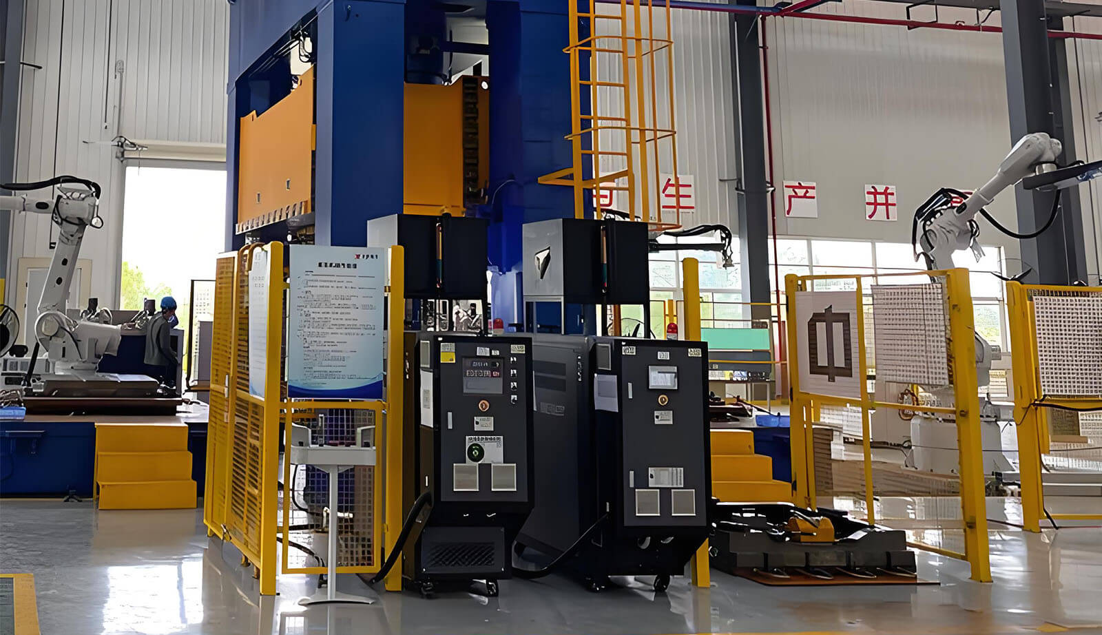
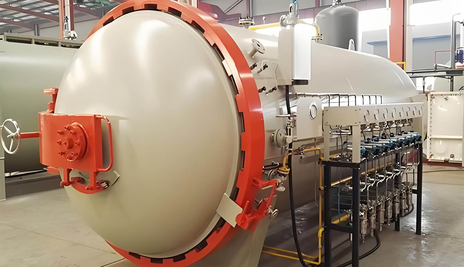
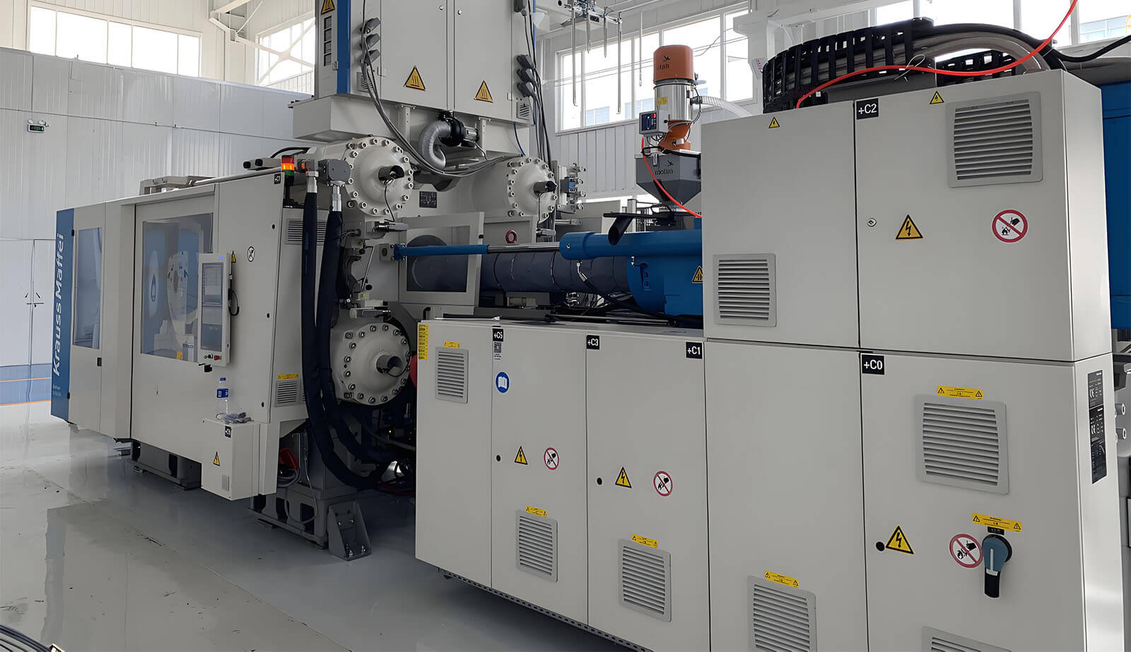
Closed-mold manufacturing approaches, such as the RTM carbon fiber process, are increasingly used in structural composite components where fiber volume fraction, corner consolidation, and void content must be tightly controlled.
For square-section tubes in particular, RTM enables more uniform resin distribution around sharp corners, improved repeatability between parts, and reduced risk of resin starvation or hidden porosity — all of which directly influence long-term durability and damage tolerance.
Roll-wrapped (prepreg or dry + resin infusion) Many commercial square tubes use roll-wrapped laminates: alternating unidirectional and woven/twill fabrics wrapped around a square mandrel, then cured. DragonPlate’s tubes sandwich the uni-directional core between inner and outer twill to support and protect it. This gives good surface finish, better edge transition support, and cosmetic appeal.
Pultrusion In pultrusion, continuous fibers/resin are pulled through a heated forming die. It offers high throughput and consistency for simple geometries—but less flexibility in fiber orientation.
Braided / multi-directional preforms Advanced research (e.g. “four-way braided thin-walled tubes”) is exploring 3D braided techniques to reduce delamination and improve multi-directional strength.
Hybrid or cold-forging composite bonding New studies look at combining carbon tubes with epoxy composite joints or cold forging techniques to improve dynamic behavior.
In selecting approach, you balance cost, flexibility, quality control, and expected performance.
Defects: the silent killers
Let me be blunt: most composite failures stem not from “insufficient strength” in the design, but from defects. Some you can’t see; some you must plan for.
- Voids or air pockets: reduce local stiffness, initiate cracks.
- Fiber misalignment / wrinkling: warp load paths and stress concentrations.
- Resin-rich zones / resin starvation: unbalanced stress transmission.
- Interlaminar delamination: layers separating under shear or bending.
- Corner delamination or edge cracking: corners are high-risk zones.
- Impacts / microcracks: even a small ding can seed failure.
Quality control must include NDT (ultrasound, thermography, X-ray, tap testing), coupon pull tests, and sample destruct tests.
One tip from experienced fabricators: always set aside a “shadow coupon” (a piece made alongside the tube) for destructive testing and correlation. Design your inspection protocols early, not after you build.
4. Real Projects and Stories That Teach More Than Theory
Stories stick; numbers fade. Here are real or semi-real narratives that reveal more than formulas.
Story: The Simons Observatory Cryogenic Strut
In the Simons Observatory (a cosmic microwave background telescope), engineers needed struts that are stiff, lightweight, thermally insulating, and survive cryogenic cycles. They used carbon fiber tubes with aluminum end caps. They discovered that the failure point was not the CFRP tube, but rather the interfaces—the end caps and mounting hardware.
They also measured thermal conduction: the carbon tubes passed only <1 mW heat load from 4 K to 1 K, meeting stringent cryogenic performance.
Lesson: your joint design, adhesive selection, thermal mismatches, and interface durability matter just as much as the tube.
Story: Automobilistikë Production Equipment Reinvented
A study on carbon composite use in automotive production equipment redesigned a steel gripper in carbon composite and aluminum hybrid form. They achieved ~60% weight reduction, better ergonomics, and robustness without excessive cost.
The twist: many in the shop environment expected heavy collisions, knocks, or misalignment. The design budgeted extra margin around harsh joints, protective covers, and replaceable elements to ensure long life. The “material novelty” was tempered by disciplined engineering.
Story: Energy absorption with defective tubes
In lab tests, composite tubes with holes (simulating defects or perforations) dropped energy absorption capabilities dramatically under axial crush. The location of holes was often more influential than their size.
This is a caution: a drilled mounting hole, fastener hole, or wiring pass-through isn’t just a benign cut—it becomes a weak point in crash, impact, or structural resilience.
5. A Design Mindset: How to Think (and Decide) with Depth
Here’s a layered way to approach specifying or designing carbon fiber square tubes—not as “pick a size and put it in,” but as a conversation between your constraints and the material’s “desires.”
Step 1: Load orchestration & hierarchy
Begin by listing all loads (primary, secondary, off-nominal). Develop a load hierarchy: which is dominant (bending? torque? axial compression? lateral load?). For each load, ask: “Which fiber direction resists this best?” Map fibers to load paths.
Step 2: Geometry & sizing — but with meanders
Choose outer size a, thickness t, length L, but anticipate adding local stiffeners, ply drops, or patches. Don’t commit to uniform thickness blindly—constrain ends and joints more heavily.
Step 3: Layup scheme with “safety margins baked in”
Design a basic stacking sequence (e.g. [0/±45/0] symmetric), but add buffer plies or hybrid plies near edges or joints. Transition gradually (e.g. 10°, 20° layers) to reduce sudden stiffness jumps and delamination risk.
Step 4: Joint, interface, and transition design
This is often where things fail:
- Use graded interfaces (transition plies) between tube and metal inserts.
- Use fillets, adhesives with matching CTE, and overlapping laminate patches.
- Place holes, slots, or cuts away from high stress zones if possible.
- Try test joints first.
Step 5: Simulation, scaling, and damage models
Don’t rely purely on classical beam theory. Use FEA models with cohesive zone modeling, fracture energy, and size effect scaling. Include potential delamination, microcracks, and progressive failure models.
Step 6: Prototyping, instrumentation, and failure learning
Prototype early. Embed strain gauges, acoustic emission sensors, or FBGs (fiber Bragg grating sensors) to detect damage. Test under real environments (temperature, humidity, impact). Let your prototypes “talk back.”
Step 7: Lifecycle, inspection, and repair strategy
Plan inspection intervals, allowable damage thresholds (e.g. allowable delamination length), and design for repair (patchability, ease of sanding, localized reinforcement). Include protective surfaces (UV coatings, edge guards) to reduce hidden damage initiation.
6. What Separates Your Article (or Your Product) from the Pack?
If you publish or market this, here’s how to make it richer than your competitors:
Embed your own data / test curves Don’t just quote generic numbers. Use your coupon test, bending vs load graphs, failure images, strain maps, FEA deflection curves.
Show the human side Include anecdotes of failures, surprises, redesigns. Show how you (or another engineer) iterated from early prototypes to robust final parts.
Layer the narrative Don’t present theory first, then application. Instead, interleave “why this matters” stories: “In one project, we thought the tube was safe, until a tiny ding caused delamination that killed performance.”
Offer design “recipes” with caveats E.g. “If you expect about 10 N·m torsion, start with a ±45° ply thickness of at least 10% of total, but boost it near edges by +20%.”
Be honest about risk & uncertainty Say: “In fatigue, we recommend ×2 safety margin; in high-temperature use, derate modulus by 20%; in impacts, inspect after any knock.”
Include illustrative visuals & annotated figures
- Ply stacking cross-sections
- Stress distribution overlay
- Failure modes with annotated cracks
- Load vs deflection curves comparing metals vs CFRP
- Scaling effect graphs (strength vs size)
- Joint interface diagrams.
Preview future trends & R&D frontiers Talk about the promise of thin-ply thermoplastics, embedded sensing (FBG, carbon fiber self-sensing), CNT interlayers, automated layup robotics, composite-metal hybrids, dhe fibër karboni të ricikluar (e.g. MCAM’s efforts at closing the loop in carbon recycling).
Include a “design decision map” A flowchart: start → define loads → pick size → choose layup → choose manufacturing → prototype → test → revise → production. Annotate decision points and failure modes.
7. Sample Outline / Rich Draft You Can Use (with Placeholders)
Here’s a possible structure you can fill. Use this as a blueprint:
Introduction
- Why square tubes — the interface between vision and constraint
- The “dialogue” metaphor: you and the material
What Lives Inside the Tube
- Ply orchestra, fiber orientations
- Manufacturing methods and their “character”
Numbers, Limits, and Scaling
- Material metrics, quasi-brittle behavior, size effects, damage modes
When It Breaks — and What It Tells You
- Delamination, fiber break, buckling, local collapse, holes, impact
Design Mindset & Strategy
- Load hierarchy, geometry, layup, joints, safety baked in
- Simulation, prototype, instrumented testing
Stories from the Field
- The Simons Observatory strut
- Automotive gripper
- Energy absorption with holes
Comparative Table: Metal vs CFRP vs Hybrid (Show stiffness per weight, fatigue life, joinability, cost factors, risk)
Trends & Future Horizons
- Thin-ply, thermoplastic composites
- Embedded sensors / health monitoring
- Robotic layup & automated QC
- Recycling, reclaimed fibers
Conclusion: The Promise & the Duty
- You are not buying “light” — you are buying a constrained, intelligent material
- Embrace the dialogue: design generously, test humbly
- Offer caution, encourage curiosity
