
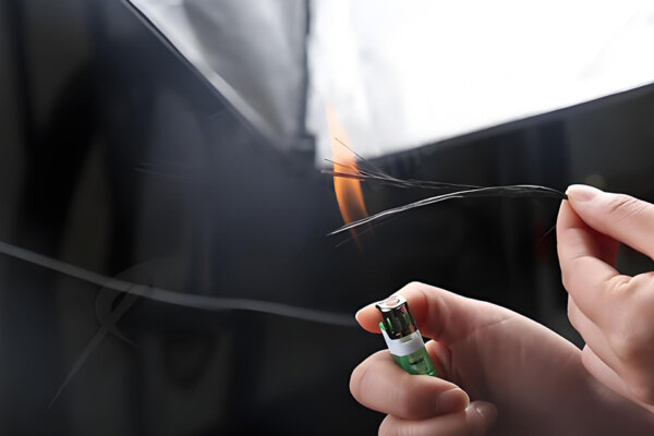

カーボンファイバー複合材料のホットプレス成形工程
当工場はP20鋼型を用いた先進的なカーボンファイバーホットプレス工程を採用し、高効率、精密、耐久性、コスト効果を実現し高品質な生産を確保しています。
私たちは、産業機器、ロボティクス、UAV、航空宇宙インテリア、海洋構造物、モータースポーツ、検査および測定システム用のカスタムカーボンファイバービーム、Iビーム、Cビーム、ボックスビームおよび構造プロファイルを製造しています。すべてのビームは、負荷方向、スパン、剛性目標、取り付け方法、表面仕上げ、生産数量を考慮して設計されています。カタログから引っ張ってくるのではありません。
もしすでに2D図面、STEP/STPファイル、またはCFRPに変換する既存のアルミニウムまたはスチールビームをお持ちであれば、私たちに送ってください。適合性を確認し、24時間以内に初期の回答を提供します。複雑なカスタムビームについては、正式な見積もりに私たちのエンジニアリングチームによる図面のレビューが必要かもしれません。
見積もりが必要ですか? 断面図、STEPファイル、または仕様書を送ってください。24時間以内に初期の適合性レビューでお返事します。 見積もりのリクエスト →
カーボンファイバービームは、カーボンファイバー強化ポリマー (CFRP) から製造される構造プロファイルであり、金属の代替品に比べて重量を減らしながら、曲げ、ねじり、または軸方向の荷重を支えるように設計されています。エンジニアが移動質量を減らし、変形を最小化し、振動減衰を改善し、鋼またはアルミニウムが提供できる以上の疲労寿命を延ばす必要がある場所で使用されます。
アルミニウム押出しとは異なり — すべての方向で同じように動作する — カーボンファイバービームは、 異方: 剛性と強度は繊維の配向に依存します。すべての繊維がその長さに沿って走っているビームは、その軸に沿って非常に剛性が高いですが、ねじりには比較的弱いです。±45°の層を持つバランスの取れたラミネートは、ねじりに対処しますが、一部の軸方向剛性をトレードオフします。レイアップスケジュールは、製造の詳細だけでなく、エンジニアリング作業の一部です。
CFRPビームが工学的応用において特に有用である2つの特性:
として カーボンファイバー複合材製造工場、私たちは産業用、 自動車、航空宇宙のお客様向けに、構造ビームの他に幅広い製品を生産しています。私たちが製造する一般的な断面プロファイルは次のとおりです: カスタムカーボンファイバーパーツ Iビーム / Hビーム
コード例
| 意味 | タイプ | I-80×40×3 |
|---|---|---|
| Iビーム | 高さ80mm、フランジ幅40mm、壁厚3mm | H-120×80×4×6 |
| Hビーム | 高さ120mm、フランジ幅80mm、ウェブ4mm、フランジ6mm | C-60×30×2 |
| Cチャンネル | C-channel | 高さ60mm、フランジ幅30mm、壁厚2mm |
| RHS-40×20×2 | 長方形中空セクション | 外寸40×20mm、壁厚2mm |
カスタムセクションについては、これらの寸法の任意の組み合わせを図面またはSTEPファイルで指定でき、それに基づいて生産に必要な工具やプロセスを評価します。
私たちが作業する典型的なサイズ範囲:
私たちが直面する最も一般的なエンジニアリングの質問は、特定のアプリケーションにおいてアルミニウムや鋼からカーボンファイバーに切り替えることが意味を持つかどうかです。ここに直接の比較があります:
| プロパティ | カーボンファイバー (CFRP) | 6061-T6アルミニウム | 構造用鋼 |
|---|---|---|---|
| 密度 | ~1.55–1.60 g/cm³ | 2.70 g/cm³ | 7.85 g/cm³ |
| 引張強さ(繊維方向) | 600–1,500 MPa(グレード依存) | 310 MPa | 400–550 MPa |
| 引張モジュラス(繊維方向) | 70–300 GPa(グレード依存) | 69 GPa | 200 GPa |
| 比剛性(E/ρ) | 主荷重方向で最適化された場合、アルミニウムよりもはるかに高い | ベースライン | ~アルミニウムの約50% |
| 熱膨張(縦方向) | ~0–2 µm/m·K | ~23 µm/m·K | ~12 µm/m·K |
| 振動減衰 | 一般的にアルミニウムや鋼よりも高い;範囲はラミネートと構造に依存する | ロー | 非常に低い |
| 耐食性 | 素晴らしい | 良好(アルマイト処理) | コーティングが必要 |
| 疲労特性 | 適切に設計すれば優れた性能 | 中程度 | グッド |
| 電気伝導度 | 平面内で導電性 | 導電性 | 導電性 |
| アルミニウムとのガルバニック互換性 | 湿潤環境では隔離層が必要 | — | — |
| 機械加工 | カーバイド/ダイヤモンド工具が必要 | 標準CNC | 標準CNC |
| 接合方法 | エンジニアリングインサートを用いた接着または機械的 | 溶接、ボルト留め、リベット留め | 溶接、ボルト留め |
| カスタムプロファイルツーリング | 非標準セクションには必要 | 市販の押出成形品が利用可能 | 標準ミルセクションが利用可能 |
| 単位コスト(同等の断面積) | より高い | より低い | より低い |
ガルバニック腐食の注意: カーボンファイバーは平面内で電気的に導電性です。湿気のある環境でCFRPと素地のアルミニウムが直接接触すると、アルミニウムのガルバニック腐食を引き起こします。これはGFRPシム、隔離ワッシャー、陽極酸化インターフェース、または湿潤シーラントで管理されます — これは最初から設計し、サービス中に発見するものではありません。
カーボンファイバーが意味を持つ場合: 慣性が減少し、サイクルが早くなったり精度が向上したりする移動構造(ガントリー、ロボティクス、CMMブリッジ)、熱移動によって誤差が生じる精密構造(計測、望遠鏡のマウント)、金属が疲労や腐食により時間と共に劣化する構造、重量削減が直接的な運用影響をもたらすアプリケーション(UAVの飛行時間、モータースポーツパフォーマンス)。
金属が依然としてより実用的な選択肢である場合: 重量削減がわずかである非常に短いスパン、ラミネートレイアップに合わない複雑な3D形状の部品、工具コストが償却できない非常に少量のプロジェクト、および接点面積が非常に小さく、インサートによって生じるコストが材料の切り替えによる節約を上回るアプリケーション。
| ビームタイプ | 最適な荷重シナリオ | 主要な利点 | 主なトレードオフ |
|---|---|---|---|
| — 垂直ウェブで接続されたフランジ;単軸曲げ荷重に効率的;曲げ応力が最も高い場所に材料を配置 | 単一軸の曲げ; 長スパン | 曲げ剛性のための材料の最も効率的な使用 | 閉じたボックスよりも低いねじり剛性 |
| — 三面が開いているセクション;表面に平らにボルト留めしたり取り付けたりしやすい;機械フレーム、レールガイド、およびリブ構造で一般的 | エッジ取り付けのフレーム; レールガイド; リブ構造 | 表面に平らにボルトで固定しやすい; オープンセクションによりケーブル経路が可能 | オープンセクションは低いねじり剛性を持つ |
| — 閉じた長方形または正方形の断面;最もねじり抵抗のある形状;UAVブームとロボットアームの標準 | 曲げとトーションの組み合わせ; ロボットアーム; UAVブーム | 単位重量あたりの最高のねじり剛性 | オープンセクションよりも複雑な工具 |
| 長方形 / 正方形ビーム | 一般的なフレーミング; ジグ; テストフィクスチャ | シンプルな形状; 加工と組み立てが容易 | 特定の荷重方向向けに最適化されていない |
| 金属インサート付きハイブリッドビーム | 高荷重ボルト接続; フランジ取り付けアセンブリ | 信頼できる機械的ジョイント; 設計済みのベアリング容量 | 部品あたりのコストが高い; インサート設計が必要 |
| トラス / ラティスビーム | 非常に長いスパン; 上部構造; 風荷重構造 | 質量対剛性の最適化; 風の抵抗を減少 | より複雑な組み立て; 複数のメンバー接続 |
アルミニウムまたは鋼のビームをCFRPに置き換える前、または新しいカーボンファイバー構造ビームをゼロから設計する前に、スイッチが意味を成すかどうか、ビームがどのように見えるべきかを決定する重要な設計入力は次のとおりです:
これらの入力の一部をお寄せいただければ、より具体的で有用な初期応答をお届けできます。
スパン、支持、および荷重の位置。 How long is the beam, how is it supported, and where is the load applied? A 1.5m gantry crossbeam under distributed load and a 1.5m cantilever arm under tip load require very different cross-sections and layups — the same length doesn’t mean the same design.
Bending stiffness vs. torsional stiffness. If the beam is primarily loaded in one plane, we optimize for axial stiffness with a high UD fiber content. If it experiences combined bending and torsion — typical for robotic arms, camera sliders, and UAV booms — we use a closed box section with ±45° plies to carry shear loads.
Fiber orientation and layup sequence. A beam with all 0° UD plies is the stiffest possible in the axial direction but can fail with little warning in the transverse direction. A quasi-isotropic laminate [0/45/90/-45]s is more damage-tolerant and easier to connect to surrounding structure, but heavier for the same axial stiffness. For most structural beams, we use a hybrid schedule: predominantly UD plies in the flanges for bending stiffness, ±45° plies in the web for shear, and outer cap plies for surface protection.
Wall thickness, cross-section proportions, and buckling. For thin-walled beams under compression or bending, local buckling can occur before the material reaches its failure stress. We review this during engineering assessment, especially for slender beams or those under compressive loading.
Attachment: holes, inserts, and bonding surfaces. A bolt through an unlined CFRP hole concentrates stress at the fastener and will fail in bearing at a much lower load than a properly designed insert allows. For any connection above light-duty, we recommend bonded metal inserts or local ply buildup at the attachment zone.
Operating environment. Standard epoxy resin systems hold their properties up to approximately 80–100°C. For higher-temperature environments, we select a resin system based on the material data sheet for the working temperature range. UV-exposed parts need UV-stable clear coat. Chemical exposure should be mentioned during enquiry — resin systems vary in chemical resistance.
Electrical conductivity. Carbon fiber is electrically conductive in-plane. If the application requires an electrically isolating beam — sensor mounts, RF-transparent structures, medical equipment — GFRP or hybrid CFRP/GFRP layups can address this.
This is one of the most common process questions we receive, and the answer matters for both cost and lead time.
Pultruded carbon fiber beams are produced by pulling continuous fibers through a resin bath and a heated die in a single continuous operation. The result is a constant cross-section profile with consistent properties along the full length. Pultrusion is cost-effective for high volumes of standard sections — I-beams, H-beams, C-channels, rectangular tubes — and produces a high, uniform fiber content. The limitation is geometry: the cross-section must be constant along the length, and the process does not allow local reinforcement, varying wall thickness, or integrated inserts within the beam body.
Molded carbon fiber beams — produced by autoclave, compression press, or wet layup — offer much greater design flexibility. The layup can be varied along the length, local reinforcement can be added at attachment points, metal inserts can be incorporated during manufacturing, and a visible surface finish is achievable on all faces. Molded beams are better suited to custom I-beams, C-beams, and box beams where geometry changes along the length or where the quantity doesn’t justify pultrusion tooling.
| Scenario | Better Process |
|---|---|
| Long, constant cross-section in high volume | Pultrusion (via partner) |
| Custom geometry, inserts, or visible surface | Autoclave or compression molding |
| Small quantity custom I-beam or C-beam | 圧縮成形 |
| Prototype with final production intent | Molded (same mold for production) |
| Very long structural stock (meters of profile) | Pultrusion (via partner) |
For most custom beam projects — UAV booms, gantry beams, robotic arm links, inspection fixtures — molded processes are the better starting point. We’ll identify the right process during engineering review.
| プロセス | Best Geometry | Performance Level | 工具コスト | Min. Practical Qty | Max. Length |
|---|---|---|---|---|---|
| プレプレグオートクレーブ | Complex profiles; visible surfaces | 最高 | 中–高 | 1+ | ~2,500mm |
| Compression / hot press | I-beams; C-beams; close-tolerance profiles | 非常に良い | 中–高 | 10+ | ~2,000mm |
| Wet layup + vacuum bag | Large one-offs; prototypes | グッド | ロー | 1 | ~3,000mm+ |
| Pultrusion (via partners) | Constant cross-section stock; volume | Very consistent axial properties | High (one-time) | 50m+ | Continuous |
Carbon fiber prepreg plies — typically T700 3K twill for visible surfaces, T700 UD or T800 UD for structural flanges where stiffness-to-weight is critical — are hand-laid into the mold, vacuum-bagged, and cured in an autoclave under controlled temperature and pressure. This process produces consistent consolidation and minimizes voids. It’s our standard approach for performance-critical beams, visible-surface parts, and anything requiring precisely controlled layup orientation.
For I-beams and C-channels where the flange and web geometry must be dimensionally precise and repeatable across a batch, we use matched steel or aluminum tooling under a hydraulic press. Prepreg is laid into the mold halves, and the press applies even clamping pressure during cure. This gives tighter cross-section tolerance and good part-to-part consistency — important when the beam must fit into a machine with close clearances or mate to a precision interface.
For prototypes, large single beams, or projects where budget doesn’t support autoclave tooling, wet layup with vacuum bagging is practical. Consolidation is somewhat lower than autoclave, which means slightly lower properties per unit weight, but for many structural applications the difference is within acceptable margins. We use this process where it genuinely fits the project requirements.
For long constant cross-section profiles — structural frames, rail systems, and guide tracks — pultrusion delivers consistent properties at high volume. We don’t operate pultrusion equipment in-house; for projects requiring pultruded profiles, we source through qualified partners and manage quality on your behalf.
After curing, most beams need secondary work before delivery: trimming to length, drilling mounting holes, milling slots, bonding inserts. We use carbide and diamond-tipped tooling to avoid delamination at cut edges. For production quantities, CNC drilling with fixtures ensures consistent hole position and quality. End fittings are CNC-machined to GD&T tolerances and then bonded or bolted to the beam body.
Most structural carbon fiber beams don’t fail in the beam body — they fail at the connection point. This is why we treat end fitting design as part of the beam project, not a detail to be resolved later.
For beams attaching to machine structures, gantry carriages, robotic joints, or UAV fuselages, the interface typically involves one or more of the following:
The end fitting geometry often affects the tooling design for the beam body itself. We review your attachment method during engineering assessment and flag anything that could create load path issues, insufficient bonding area, galvanic contact, or tolerance problems.
Achievable tolerance depends on the profile, length, process, and whether post-machining is included:
| 特徴 | As-produced (molded / roll-wrapped) | After CNC machining |
|---|---|---|
| Outer dimensions | ±0.2–0.5mm typical | ±0.05–0.1mm achievable |
| 肉厚 | ±0.1–0.3mm | — |
| 長さ | ±1–2mm (cut to length) | ±0.1mm |
| 穴の位置 | — | ±0.05mm with fixture |
| 真っ直ぐさ | ≤0.5mm/m typical | Depends on beam stiffness |
| Surface finish (visible) | 3K weave, glossy or matte clear coat | — |
For beams going into precision machines or inspection systems, the critical interface dimensions — hole positions, end fitting mating surfaces, rail mounting faces — are CNC-machined to the tolerances the application requires.
Standard inspection: dimensional check on critical dimensions, visual inspection for surface defects (voids, resin-rich areas, dry fiber, delamination at edges), weight check, and photographic documentation. For production batches, we issue a first-article inspection report for customer approval before running the full batch.
We don’t currently offer in-house non-destructive testing (ultrasonic C-scan or X-ray). For projects where this is specified, we can arrange third-party inspection — this should be discussed during the quotation stage as it affects cost and schedule.
We prefer to explain these before a project starts rather than after.
Impact damage is hard to detect. Carbon fiber composites don’t yield like metal before failing — they fracture. A tool dropped onto a beam or a lateral impact can cause internal delamination that doesn’t show on the surface but reduces structural capacity. If the beam operates in an impact-prone environment, we can discuss damage-tolerant design measures, protective covers, or whether a metal alternative is more practical.
Point loads require inserts or load-spreading provisions. A bolt pulled through a thin CFRP wall without a proper insert will fail in bearing at a fraction of the load a threaded insert can carry. Any bolted connection under significant load needs to be designed with this in mind from the start.
Sharp internal corners complicate layup. カーボンファイバーのプリプレグは、約3mm未満の内半径に対して、 voids や樹脂豊富なゾーンのリスクなしにはきれいに適合しません。この点を指摘し、デザインレビューの際に半径の調整を提案します。
一体成型の長さは、プロセスに制限されています。 私たちの設備は、ほとんどのプロファイルに対して約2,500mmまで対応可能です。より長いスパンについては、パートナーを通じたプルテュードプロファイル(一定断面用)、スプライスされたセクション、またはトラスデザインがスパンを短い部材に分けます。
湿潤環境における CFRP とアルミニウムの接触は、電食を引き起こします。 これは設計要件であり、施工の詳細ではありません。初めから接合部に絶縁を組み込む必要があります。
カスタムIビームおよびCビームは、専用のツーリングが必要です。 標準サイズの構造的長方形チューブの場合、既存のマンドレルがツーリングコストとリードタイムを削減します。カスタムIビームやCチャンネル断面では、ツーリングは一度限りの投資であり、生産計画によって正当化される必要があります。
以下は、私たちの製造経験に基づいた匿名化されたプロジェクトパターンです。顧客名、図面、特定の寸法は公開されていません — ほとんどのカスタム構造ビームプロジェクトはNDAの対象です。
設計の目標は、1,200mmのアルミニウムガントリー横梁の移動質量を減らし、高速通過中の動的沈降挙動を改善することでした。私たちは、曲げ剛性のために主に上部と下部フランジにUDプリプレグを使用したカーボンファイバーボックスビームを製造しました。全体に±45°の層を使用し、トルショナル安定性を持たせ、ガントリーカートリッジインターフェースのためにCNCで穴が開けられたアルミニウムエンドプレートを接合しました。CFRPの低CTEは、長時間の生産シフト中の温度関連の寸法変動を減少させるために選ばれました。プロセス: プリプレグオートクレーブ。
商業用UAVプログラムには、ペイロードを持ち上げるマルチローター用の構造ブームが必要で、両端にはモーター取り付けおよび機体取り付け用のステンレススチール製ネジ付き挿入材がありました。プロジェクトは、飛行検証のための4つのプロトタイプブームから始まりました。私たちは、マンドレルの上にT700プリプレグをリール巻きすることでブームを製造し、挿入部の追加のUDプライの積層を行いました。硬化後、ステンレス挿入材を構造用接着剤で接合し、最終位置にCNCで穴あけしました。プロトタイプが承認された後、プログラムはバッチ生産に移行しました。図面承認から最初のプロトタイプ納品まで:約4週間。
レーシングチームは、排気システムの近くにある構造ビームが必要で、持続的な作業温度が標準的なエポキシの限界を超える必要がありました。私たちは、アプリケーション温度範囲のデータシートの特性に基づいて、高Tg樹脂システムを選択し、鋼製金型を使って圧縮成形でビームを製造しました。表面: 3Kツイルのマットクリアコート。この種の高温エンジニアリング作業は、私たちのより広範な カーボンファイバーモータースポーツおよび自動車プログラムの一環です。.
天文機器メーカーは、昼夜の温度変化による追跡誤差を防ぐためのモーター式望遠鏡マウント用の構造部材が必要でした。CFRPの低縦方向CTEが主要な設計要件でした。私たちは、主に0° UDレイアップで長方形のチューブセクションを製造し、軸方向の剛性を最大化し、縦方向の熱膨張を最小化しました。外表面はサンディングされたままにしておき、顧客が自分の陽極酸化アルミニウムインターフェースブラケットをGFRP絶縁ワッシャーで適用できるようにしました。
産業用オートメーションとロボティクス。 ガントリー横梁、リニアモーターカートリッジ、ロボットアームリンク、SCARAクロスマンバー、およびデルタロボットアーム。これらのシステムにおける移動質量の削減は、サイクルタイムの短縮、モーターのトルク要件の低下、および位置の再現性向上に貢献できます。低CTEは、熱変動が精度に影響を与える精密検査システムにも利益をもたらします。
UAVおよびドローン構造。 固定翼ウィングスパー、マルチローターアームおよびブーム、ペイロードレール、機体ロングロン。私たちは、商業用UAVプログラムのプロトタイプ段階と小ロット生産でチームと協力しています。
航空宇宙および航空機構造。 キャビンフレーム、シート構造、機器ラック、および非主要構造部材。専用の航空機Cビームおよび構造プロファイルアプリケーションについては、私たちの カーボンファイバー航空機Cビームページを参照してください。私たちは主要な航空機構造用部品を認証しておらず、その違いをすべての航空宇宙における問い合わせで明確にしています。
海洋およびオフショア。 スパー、ブーム、アウトリガーアーム、およびハッチフレーム構造。耐腐食性と重量削減の組み合わせは、カーボンファイバーをレース用ヨット、テンダー、そして塩水とサイクル荷重にさらされるオフショア設備にとって実用的にします。
モータースポーツおよびレーシング。 構造シャーシ部材、ロールケージ挿入材、スプリッターサポートアーム、アンダートレイ構造、およびサスペンションピックアップ補強部。私たちは、 自動車およびトラック用カーボンファイバー部品を製造しています。 これは、パフォーマンス車両複合材の一環です。 カーボンファイバー製バイク部品 計測および精密測定。
CMMブリッジ、プロフィロメーターアーム、望遠鏡チューブアセンブリ、および精密ステージビーム。カーボンファイバーは、熱変動や弾性変位が測定誤差を生む場合にうまく適しています。 印刷、テキスタイルおよび変換機械。
ドクターブレード、ダンサー ローラー、ウェブガイドビーム、および印刷シリンダーサポート。高速ウェブ処理機械では、カーボンファイバーが振動や慣性を減少させ、印刷登録を改善し、ウェブエッジの振動を減らします。 カーボンファイバーグレード
| オプション | 利用可能な選択肢 |
|---|---|
| T300, T700, T800, M40J または特性によって指定された同等品 | ファイバー形式 |
| UDプリプレグ(最高の軸方向剛性)、3K平織り、3Kツイル、12K大型トウ、スプレッドトウ | レイアップの方向 |
| 0° UD優勢、±45°、準等方性 [0/45/90/-45]s、または負荷ケースに応じたハイブリッド | 標準エポキシ、高Tgエポキシ、難燃性エポキシ — 作業温度とデータシートに応じて選択 |
| 樹脂システム | 光沢クリアコート、マットクリアコート、UV保護クリアコート |
| Surface finish (visible) | 表面仕上げ(構造/接着) |
| 生、接着用のサンディング、プライミング | ナチュラルカーボンウィーブ(クリアコート)、ソリッドペイント(RALを指定またはサンプルを供給)、カスタム |
| カラー | 金属挿入材 |
| アルミニウム、ステンレス鋼、チタン — 接合または共成形 | アルミニウム、ステンレス鋼、チタン — 接着または共成形 |
| エンドフィッティング | 図面およびGD&T公差に基づいて精密加工されたアルミニウムまたはスチール製エンドフィッティング |
| galvanic isolation | GFRPシム層、絶縁ワッシャー、またはCFRPとアルミニウムの接合部に使用される陽極酸化されたインターフェース |
| 金型材料 | 複合材料金型(プロトタイプ/少量)、アルミニウム金型(中量)、P20鋼金型(大容量/厳密な公差) |
| 二次加工 | CNCドリリング、フライス加工、スロット加工、タッピング;挿入物が位置に結合され加工される |
| 検査および文書化 | 寸法チェック、目視検査、初回生産報告、重量公差、材料トレーサビリティ |
| インフォメーション | その重要性 |
|---|---|
| 2D図面またはSTEP/STPファイル | 金型の形状、レイアップアクセス、およびCNC操作を評価します |
| 断面タイプおよび寸法 | ツーリング、繊維スケジュール、および剛性を決定する |
| 肉厚 | 構造性能、重量、およびツーリングに影響します |
| 部品あたりのビーム長 | プロセスの選択と出荷方法を決定する |
| 荷重条件、目標剛性、またはたわみ制限 | 繊維の向きと断面設計を促進します |
| 各端の取り付け/接続方法 | 挿入物のタイプ、エンドフィッティングの設計、および局所強化を決定する |
| 数量:プロトタイプ/パイロットバッチ/生産 | 金型投資と単位価格を決定する |
| 表面仕上げと色 | 加工ステップとコストに影響します |
| 作業温度範囲 | 樹脂システムを決定する |
| 重要な特徴の公差 | ツーリング投資と後加工スコープを決定する |
| 電気的絶縁が必要ですか? | GFRP層またはハイブリッドレイアップが必要かどうかを決定する |
| スキャン用の既存のサンプルまたは部品はありますか? | 図面がない場合でも3Dスキャンが利用可能です |
すべてがまだ揃っていない場合(例えば、正式な図面がないアルミビームがある場合)、持っているものを送ってください。重要な寸法を含むスケッチ、測定の写真、スキャン用の物理サンプル、またはアプリケーションの説明とパフォーマンスターゲットから作業できます。
ステップ1 - 必要事項を提出してください。 図面、STEPファイル、またはプロジェクトの説明をメールしてください。簡単な問い合わせの場合は、24時間以内に初回回答を提供します。
ステップ2 - エンジニアリングのレビューと見積もり。 製造可能性、プロセス適合性、および接続設計のために設計をレビューし、性能、コスト、実行可能性に影響するものをフラグ付けします。ツーリングコスト(該当する場合)、単価、確認されたリードタイムを含む正式な見積もりを受け取ります。
ステップ3 - ツーリング開発。 専用のツーリングが必要なカスタムプロファイルのために、承認された図面から金型を設計・製造します。ツーリングは私たちの施設に保管され、将来の再注文には追加のツーリングコストなしで利用可能です。
ステップ4 - 初回サンプル。 初回部品を製造し、寸法検査結果や写真を共有し、バッチ生産に進む前にあなたの承認を待ちます。
ステップ5 - バッチ生産と検査。 定義されたチェックポイントでの検査を伴う生産。検査結果と写真は、合意された品質計画に従って文書化されます。
ステップ6 - パッケージングと出荷。 長いビームは、内部サポート、フォームパディング、必要に応じて木製の箱にパッキングされます。私たちは定期的に米国、英国、ドイツ、カナダ、オーストラリアに出荷し、すべての輸出文書を取り扱います。
私たちは、炭素繊維複合材料製造工場であり、商社でも在庫再販業者でもありません。 私たちの工場と生産能力についてもっと知る →
私たちの施設ではオートクレーブ、圧縮プレス、CNC加工設備を稼働させ、さまざまなプログラムにわたってCFRP部品を製造しています。構造ビームを超えて、私たちの カスタム炭素繊維製造サービス covers everything from one-off prototypes to OEM batch production across a wide range of part types and industries.
What this means for a structural beam project:
Both profiles have the same cross-section shape — two flanges connected by a vertical web. The naming convention differs by proportion: I-beams typically have narrower flanges relative to the web height, while H-beams have flanges closer in width to the total height, giving a more symmetrical appearance. In carbon fiber, this distinction is less standardized than in structural steel sections; we produce whichever flange and web proportions your design specifies.
On a weight-for-weight basis, the tensile strength and stiffness of carbon fiber along the fiber direction are significantly higher than structural steel. In absolute terms (per unit of cross-section area), the comparison depends on fiber grade, layup, and load direction. For most structural beam applications, the more useful metric is bending stiffness-to-weight, where carbon fiber performs well when the beam is designed to take advantage of its directional properties.
Rarely at the same dimensions. Carbon fiber and aluminum have different modulus values and very different directional behavior, so a dimensional swap will change deflection behavior. Most aluminum-to-CFRP conversions involve redesigning the cross-section to achieve the same or better stiffness at lower weight — which typically means different section proportions, wall thickness, and layup. If you share your current aluminum beam specification and the stiffness or deflection requirement, we can help with this assessment.
Yes, and this is one of the most common structural beam applications we see. CFRP gantry crossbeams reduce moving mass, which allows higher acceleration and deceleration without exceeding motor limits, and reduces settling time after each positioning move. The low CTE also reduces thermal-induced positioning drift in temperature-varying production environments. The specific design — cross-section, layup, end fitting geometry — depends on span, rail mounting method, deflection target, and machine dynamics.
There is no universal answer — it depends on the load case. A practical starting point for a beam loaded primarily in bending is predominantly 0° UD plies in the flanges (where bending stress is highest) combined with ±45° plies in the web (for shear capacity and torsional resistance), and outer cap plies for surface quality. If the beam also carries torsional load, we increase the ±45° content. If axial compressive load is significant, 90° plies may be added to resist local buckling. The final layup schedule is determined during engineering review after we understand your load case.
Yes. If you don’t have drawings, we can work from a physical sample, photographs with key dimensions, or a 3D scan. For a true aluminum-to-carbon conversion, we’ll also need to understand the load case and target stiffness or deflection — because a carbon fiber beam is not usually a direct dimensional replacement. The geometry is typically redesigned to optimize for the material’s properties.
A drawing speeds up the process, but it’s not required to start. A sketch with the key dimensions — cross-section type, height, flange width, wall thickness, length, and attachment point locations — is enough for an initial feasibility assessment. If you have an existing part but no drawing, we can 3D scan it.
Yes. Prototype and first-article orders are a standard part of our process. For tooled profiles, the prototype is built on the same mold used for production, so it is fully representative of the final part.
For roll-wrapped tubes in common sizes, there is no hard minimum — single pieces are possible. For custom-tooled profiles, the tooling cost is a fixed element that makes very small runs less economical. We’ll be direct about whether the project is feasible at your quantity.
No. Tooling is a one-time cost. The mold stays at our facility and is available for all reorders without additional tooling charges. The tooling amortization terms are stated in the quotation.
Yes, with the correct tooling and technique. We use carbide or diamond-tipped drills at controlled feed rates, with backup support on the exit face to prevent delamination at breakthrough. For production quantities, CNC drilling with fixtures ensures consistent hole position and edge quality.
No. CFRP cannot be welded. Joints are made by structural adhesive bonding, mechanical fasteners through designed inserts, or a combination of both. For structural joints that need to be disassembled, bonded metal inserts with threaded fasteners are the standard approach.
For standard rectangular tubes in common sizes: typically 1–3 weeks. For custom profiles requiring new tooling: approximately 3–5 weeks for first-article samples after drawing approval, then 2–4 weeks for batch production. Confirmed timelines are included in every quotation.
Yes. We provide material traceability documentation for the carbon fiber prepreg used in production. For projects requiring third-party mechanical testing of produced parts, this should be discussed and agreed during the quotation stage, as it affects cost and lead time.
Isolate the contact interface. Options include a GFRP shim between the carbon beam and the aluminum mounting surface, anodized aluminum at the interface, isolation washers at each fastener, or a wet sealant in the joint. The right approach depends on the joint geometry and level of environmental exposure. We’ll specify isolation measures as part of the end fitting design where your assembly creates a CFRP-to-aluminum contact in a potentially wet or outdoor environment.
Send your drawing or STEP file to [email protected] or use the contact form below. Include cross-section dimensions, wall thickness, length, quantity, surface finish requirements, and any end fitting or mounting details. We’ll respond with an initial feasibility review within 24 hours. For complex custom beams, a formal quotation follows after drawing review by our engineering team.
当工場はP20鋼型を用いた先進的なカーボンファイバーホットプレス工程を採用し、高効率、精密、耐久性、コスト効果を実現し高品質な生産を確保しています。
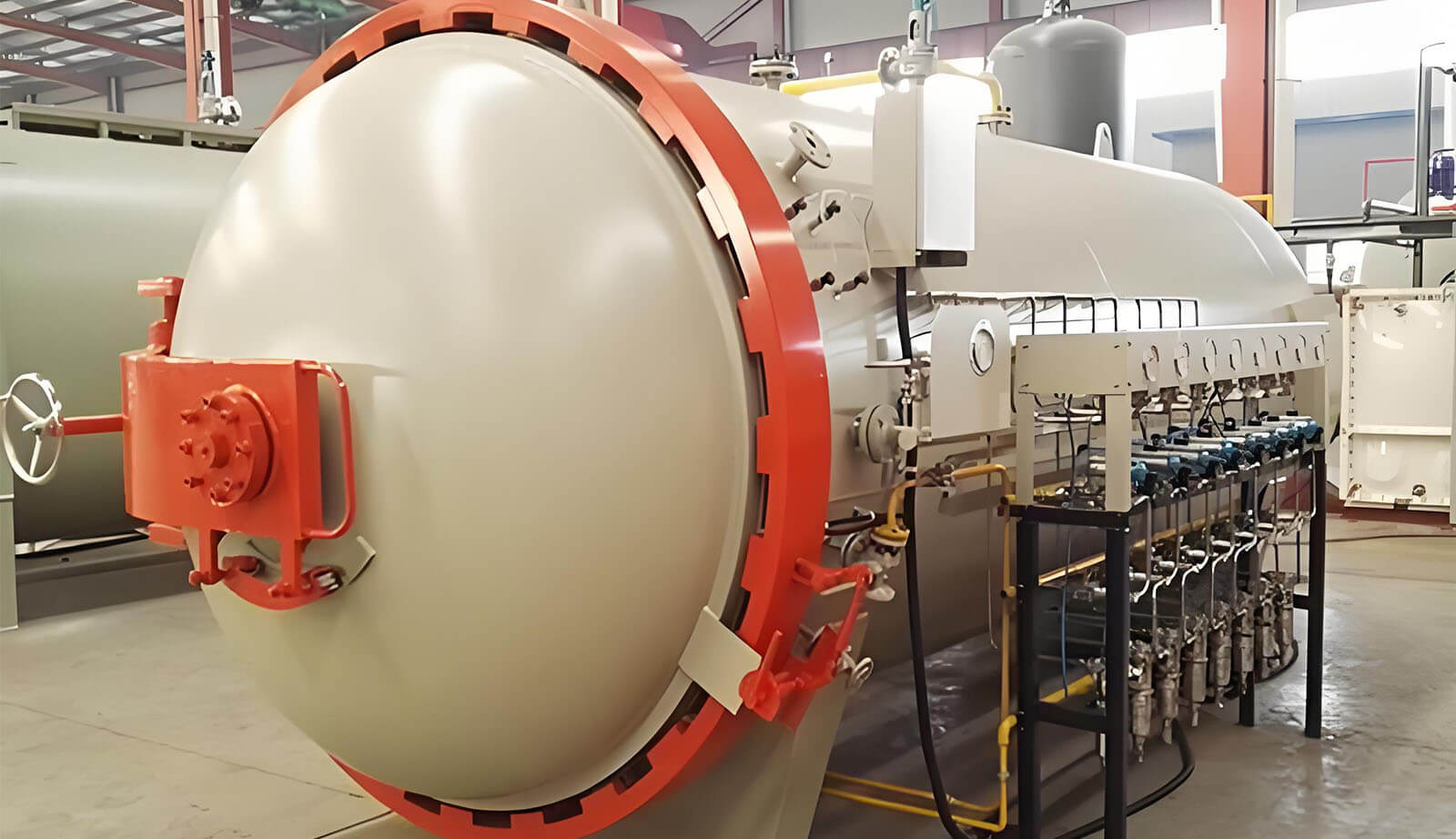
当工場は100台以上の高圧加熱オートクレーブを稼働させ、アルミ型と真空誘導を用いて精密にカーボンファイバーを成形しています。高温・高圧により強度と安定性、完璧な品質が向上します。
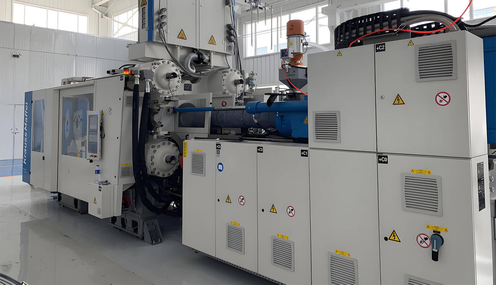
当社のカーボンファイバー研究センターは、新エネルギー、知能化、軽量設計の革新を推進し、先進的な複合材料とクラウスマッフェイ ファイバーフォームを使用して最先端かつ顧客志向のソリューションを提供します。
経験豊富なカーボンファイバー製品工場からのよくある質問への回答をご案内します。
自動車部品、オートバイ部品、航空宇宙部品、海洋アクセサリー、スポーツ用品、産業用途など、幅広いカーボンファイバーコンポーネントを製造しています。
主に高品質のプリプレグカーボンファイバーと大トウカーボンファイバー強化高性能複合材料を使用し、強度、耐久性、軽量特性を確保しています。
はい、当社の製品はUV保護仕上げが施されており、長持ちする耐久性を保ち、光沢のある外観を維持します。
はい、当社の設備と機器は精度と品質を維持しながら大型カーボンファイバーコンポーネントの製造が可能です。
カーボンファイバー製品の利点は何ですか?
カーボンファイバーは優れた強度対重量比、耐腐食性、剛性、熱安定性、そして洗練された現代的な外観を提供します。
自動車、オートバイ、航空宇宙、海洋、医療、スポーツ、工業分野に対応し、軽量で高性能なカーボンファイバー部品を提供しています。
はい、提供しております カスタムカーボンファイバー 独自のデザイン、サイズ、パターンを含む、お客様の仕様に合わせたソリューションです。
オートクレーブ成形、ホットプレス、真空バッグ成形などの先進技術を用い、精度、安定性、品質を確保した製品づくりを行っています。
耐久性と高精度を備えたアルミ型およびP20鋼型を使用し、複雑で精密なカーボンファイバー部品を製造しています。
寸法精度、材料の完全性、性能試験など厳格な品質管理を実施し、業界基準を満たしています。