
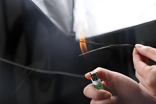

탄소 섬유 복합재료 핫 프레싱 성형 프로세스
우리 공장은 고효율, 정밀도, 내구성 및 비용 효율성을 보장하는 P20 강철 몰드를 사용하여 첨단 탄소 섬유 핫 프레스 공정을 운영하고 있습니다.
우리는 산업 장비, 로봇, UAV, 항공 우주 내부, 해양 구조물, 모터스포츠 및 검사 및 측정 시스템을 위한 맞춤형 탄소 섬유 빔, I-빔, C-빔, 박스 빔 및 구조 프로파일을 제조합니다. 모든 빔은 하중 방향, 경량 스팬, 강성 목표, 장착 방법, 표면 마감 및 생산 수량에 맞게 엔지니어링되며, 재고 카탈로그에서 끌어오지 않습니다.
이미 2D 도면, STEP/STP 파일 또는 CFRP로 변환 중인 기존 알루미늄 또는 강철 빔이 있다면, 저희에게 보내주시면 타당성을 확인하고 24시간 이내에 초기 응답을 드리겠습니다. 복잡한 맞춤형 빔의 경우, 공식 견적には 도면 검토가 필요할 수 있습니다.
견적이 필요하신가요? 단면 도면, STEP 파일 또는 사양을 보내주세요. 24시간 이내에 초기 타당성 검토로 응답하겠습니다. 견적 요청 →
탄소 섬유 빔은 탄소 섬유 강화 폴리머(CFRP)로 제조된 구조 프로파일로, 금속 대안에 비해 무게를 줄이면서 굽힘, 비틀림 또는 축 방향 하중을 지탱하도록 설계되었습니다. 이는 엔지니어들이 이동 질량을 줄이고, 처짐을 최소화하고, 진동 감쇄를 개선하거나 강철이나 알루미늄으로는 제공할 수 없는 피로 수명을 연장해야 할 때 사용됩니다.
알루미늄 압출과는 달리 - 모든 방향에서 동일하게 작동하는 - 탄소 섬유 빔은 이방성: 강성과 강도는 섬유 방향에 따라 다릅니다. 모든 섬유가 길이 방향으로 배열된 빔은 해당 축 방향으로 굽힘에 매우 강하지만 비틀림에는 상대적으로 약합니다. ±45° 적층 구조는 비틀림을 더 잘 처리하지만 일부 축 방향 강성을 절충합니다. 적층 일정은 제조 세부사항이 아닌 엔지니어링 작업의 일부입니다.
CFRP 빔을 엔지니어링 애플리케이션에서 특히 유용하게 만드는 두 가지 속성:
로서 탄소 섬유 복합재 제조 공장, 우리는 산업, 자동차 및 항공우주 고객을 위한 구조 빔과 함께 다양한 제품을 생산합니다. 우리가 만드는 가장 일반적인 단면 프로파일은: 맞춤형 탄소 섬유 부품 I-빔 / H-빔
코드 예시
| 의미 | 유형 | I-80×40×3 |
|---|---|---|
| I-빔 | 높이 80mm, 플랜지 너비 40mm, 벽 두께 3mm | H-120×80×4×6 |
| H-빔 | 높이 120mm, 플랜지 너비 80mm, 웹 4mm, 플랜지 6mm | C-60×30×2 |
| C-채널 | C-channel | 높이 60mm, 플랜지 너비 30mm, 벽 두께 2mm |
| RHS-40×20×2 | 직사각형 홀섹션 | 40×20mm 외부, 2mm 벽 |
맞춤형 섹션의 경우 도면 또는 STEP 파일에서 이러한 치수의 조합을 지정할 수 있으며, 이를 생산하기 위해 필요한 도구 및 공정을 평가합니다.
우리가 작업하는 일반 크기 범위:
우리가 접하는 가장 일반적인 기술 질문은 특정 응용 프로그램에서 알루미늄이나 강철에서 탄소 섬유로 전환하는 것이 타당한지에 대한 것입니다. 직접 비교는 다음과 같습니다:
| 속성 | Carbon Fiber (CFRP) | 6061-T6 알루미늄 | 구조용 강철 |
|---|---|---|---|
| 밀도 | ~1.55–1.60 g/cm³ | 2.70 g/cm³ | 7.85 g/cm³ |
| 인장 강도(섬유 방향) | 600–1,500 MPa (등급 의존) | 310 MPa | 400–550 MPa |
| 인장 모듈러스(섬유 방향) | 70–300 GPa (등급 의존) | 69 GPa | 200 GPa |
| 비강성(E/ρ) | 주하중 방향에서 최적화되면 알루미늄보다 상당히 높음 | 기준선 | ~50%의 알루미늄 |
| 열 팽창(종방향) | ~0–2 µm/m·K | ~23 µm/m·K | ~12 µm/m·K |
| 진동 감쇠 | 일반적으로 알루미늄이나 강철보다 높음; 정도는 적층 및 구조에 따라 달라짐 | 낮은 | 매우 낮음 |
| 내식성 | 우수 | 양호(양극 산화 처리) | 코팅이 필요함 |
| 피로 거동 | 적절히 설계되면 우수함 | 보통 | Good |
| 전기 전도성 | 이차 전도성 | 전도성 | 전도성 |
| 알루미늄과의 갈바닉 호환성 | 습한 환경에서 절연층 필요 | — | — |
| 가공 | 탄화물/다이아몬드 공구 필요 | 표준 CNC | 표준 CNC |
| 결합 방법 | 설계된 인서트를 가진 접착 또는 기계적 결합 | 용접, 볼트 체결, 리벳 | 용접, 볼트 체결 |
| 맞춤형 프로파일 도구 | 비표준 섹션에 필요함 | 기성 압출물 이용 가능 | 표준 제철 섹션 이용 가능 |
| 단가(동등 단면) | 더 높음 | Lower | Lower |
갈바닉 부식 주의 사항: 탄소 섬유는 평면에서 전기 전도성이 있습니다. 습하거나 젖은 환경에서 CFRP와 노출된 알루미늄의 직접 접촉은 알루미늄의 갈바닉 부식을 초래합니다. 이는 GFRP 쉬임, 절연 와셔, 아노다이즈 인터페이스 또는 습식 실란트로 관리해야 하며, 시작부터 설계해야 하고 서비스 중에 발견해서는 안 됩니다.
탄소 섬유가 타당할 때: 관성 감소로 인해 더 빠른 사이클 또는 더 나은 정확성이 필요한 이동 구조(가니트, 로봇, CMM 브리지), 열 이동으로 인해 오류가 발생하는 정밀 구조(측정, 망원경 장착), 피로 또는 부식으로 인해 시간이 지남에 따라 금속이 저하되는 구조, 그리고 중량 감소가 운영에 직접적인 영향을 미치는 응용 프로그램(UAV 비행 시간, 모터스포츠 성능).
여전히 금속이 더 실용적인 선택인 경우: 중량 절감이 미미한 매우 짧은 경간, 적층 배치에 적합하지 않은 복잡한 3D 기하학을 가진 부품, 도구 비용을 분산할 수 없는 매우 소량 프로젝트, 그리고 인서트가 자재 전환으로 절감된 비용보다 더 많은 비용을 추가하는 경우에 집중된 하중이 있는 매우 작은 접촉 면적.
| 빔 유형 | 최고 적재 시나리오 | 주요 장점 | 주요 트레이드오프 |
|---|---|---|---|
| — 수직 웹으로 연결된 플랜지; 단일 축 굽힘 하중에 효율적이며, 굽힘 응력이 가장 높은 곳에 재료를 배치합니다. | 단축 축 굽힘; 긴 거리 | 구부림 강성을 위한 가장 효율적인 소재 사용 | 폐쇄형 박스보다 낮은 비틀림 강성 |
| — 세 면이 열린 섹션; 표면에 평평하게 부착하기 쉬움; 기계 프레임, 레일 가이드 및 리브 구조에서 일반적입니다. | 가장자리 장착 프레임; 레일 가이드; 리브 구조 | 표면에 평평하게 볼트 체결하기 쉬움; 열린 섹션은 케이블 라우팅을 허용 | 열린 섹션은 낮은 비틀림 강성을 가짐 |
| — 닫힌 직사각형 또는 정사각형 섹션; 비틀림 저항성이 가장 높은 기하학적 구조; UAV 붐과 로봇 팔의 표준입니다. | 굽힘 및 비틀림 조합; 로봇 팔; UAV 붐 | 단위 중량당 가장 높은 비틀림 강성 | 개방형 섹션보다 더 복잡한 도구 제작 |
| 직사각형 / 정사각형 빔 | 일반 프레임; 지그; 시험 장치 | 단순한 기하학; 가공 및 조립이 쉬움 | 특정 하중 방향에 최적화되어 있지 않음 |
| 금속 삽입물이 있는 하이브리드 빔 | 고하중 볼트 연결; 플랜지 장착된 조립체 | 신뢰할 수 있는 기계적 조인트; 설계 내의 베어링 용량 | 부품당 비용이 높음; 삽입물 설계 필요 |
| 트러스 / 격자 빔 | 매우 긴 거리; 오버헤드 구조; 바람에 의한 하중 구조 | 질량 대 강성 최적화; 바람 저항 감소 | 더 복잡한 조립; 여러 구성원 연결 |
알루미늄 또는 강철 빔을 CFRP로 교체하거나 새로운 탄소 섬유 구조 빔을 처음부터 설계하기 전에, 이러한 주요 설계 입력이 전환이 의미 있는지와 빔의 형태를 결정합니다:
이러한 입력의 부분적인 사진이라도 문의와 함께 공유해 주시면, 더 구체적이고 유용한 초기 응답을 제공할 수 있습니다.
스팬, 지지대 및 하중 위치. 빔의 길이는 얼마나 되고, 어떻게 지지되며, 하중은 어디에 적용됩니까? 분산 하중을 받는 1.5m 가컨트리 크로스빔과 팁 하중을 받는 1.5m 캔틸레버 암은 매우 다른 단면과 레이업을 필요로 합니다. 같은 길이가 반드시 같은 디자인을 의미하지는 않습니다.
굽힘 강성 대 비틀림 강성. 빔이 주로 한 평면에서 하중을 받는 경우, 우리는 높은 UD 섬유 함량으로 축 방향 강성을 최적화합니다. 로봇 팔, 카메라 슬라이더, UAV 붐에 일반적인 굽힘과 비틀림이 결합된 경우 — 우리는 전단 하중을 지탱하기 위해 ±45° 플라이가 있는 닫힌 박스 단면을 사용합니다.
섬유 방향 및 레이업 순서. 모든 0° UD 플라이가 있는 빔은 축 방향에서 가능한 가장 강성이지만, 횡 방향에서는 경고 없이 실패할 수 있습니다. 불완전한 등방성 적층 [0/45/90/-45]s는 손상에 더 강하고 주변 구조에 연결하기 더 쉬우나, 같은 축 방향 강성에 대해서는 더 무겁습니다. 대부분의 구조 빔에 대해, 우리는 하이브리드 일정 공정을 사용합니다: 굽힘 강성을 위해 플랜지에 주로 UD 플라이를 사용하고, 전단을 위해 웹에 ±45° 플라이를 사용하며, 표면 보호를 위해 외관 캡 플라이를 사용합니다.
벽 두께, 단면 비율 및 좌굴. 압축 또는 굽힘 하중을 받는 얇은 벽 빔의 경우, 소재가 파단 응력을 초과하기 전에 국부적인 좌굴이 발생할 수 있습니다. 우리는 이것을 엔지니어링 평가 중에 검토하며, 특히 가늘거나 압축 하중을 받는 빔에 대해 검토합니다.
부착물: 구멍, 인서트 및 접착면. 비가공 CFRP 구멍을 통해 볼트를 삽입하면 패스너에 응력이 집중되어 올바르게 설계된 인서트가 허용하는 것보다 훨씬 낮은 하중에서 베어링에서 실패할 것입니다. 경량 토대 이상의 모든 연결에 대해, 우리는 접착 금속 인서트 또는 부착 지점에서의 국부적 플라이 증축을 권장합니다.
작업 환경. 표준 에폭시 수지 시스템은 약 80-100°C까지 그 성질을 유지합니다. 더 높은 온도 환경의 경우 작업 온도 범위에 대한 자료 데이터 시트에 따라 수지 시스템을 선택합니다. UV에 노출된 부품에는 UV 안정성이 있는 클리어 코트가 필요합니다. 화학 노출은 문의 시 언급해야 합니다 — 수지 시스템은 화학 저항이 다양합니다.
전기 전도성. 탄소 섬유는 평면 내에서 전기 전도성이 있습니다. 응용 분야가 전기를 절연하는 빔 — 센서 장착, RF 투명 구조물, 의료 장비 — 이 필요한 경우, GFRP 또는 하이브리드 CFRP/GFRP 레이업이 이를 해결할 수 있습니다.
이것은 우리가 받는 가장 일반적인 프로세스 질문 중 하나이며, 그 대답은 비용과 리드 타임 모두에 중요합니다.
풀트루드 탄소 섬유 빔 은 연속 섬유를 수지 욕조와 열 성형기 통과시켜 단일 계속적인 작업으로 생산됩니다. 결과는 전체 길이에 걸쳐 일관된 특성을 가진 일정한 단면 프로필입니다. 풀트루전은 표준 섹션 — I-빔, H-빔, C-채널, 직사각형 튜브 — 의 높은 볼륨에 대해 비용 효율적이며 높은 uniform 섬유 함량을 생성합니다. 제한 사항은 기하학적 형태입니다: 단면은 길이 동안 일정해야 하며, 프로세스에서 국부적 보강, 벽 두께의 변동, 또는 빔 본체 내에 통합된 인서트를 허용하지 않습니다.
성형된 탄소 섬유 빔 — 오토클레이브, 압축 프레스 또는 젖은 레이업으로 생산 — 더 큰 디자인 유연성을 제공합니다. 레이업은 길이에 따라 달라질 수 있으며, 부착 지점에 국부적 보강을 추가할 수 있고, 제조 중에 금속 인서를 통합할 수 있으며, 모든 면에서 가시적인 표면 마감이 가능합니다. 성형된 빔은 길이에 따라 기하학적 변화가 있거나 수량이 풀트루전 도구를 정당화하지 않는 맞춤형 I-빔, C-빔 및 박스 빔에 더 적합합니다.
| 시나리오 | 더 나은 프로세스 |
|---|---|
| 긴 일정한 단면, 고부하 투입 | 풀트루전 (파트너를 통해) |
| 맞춤 기하학, 인서트 또는 가시적인 표면 | 오토클레이브 또는 압축 성형 |
| 소량 맞춤 I-빔 또는 C-빔 | 압축 성형 |
| 최종 생산 의도를 가진 프로토타입 | 성형 (생산을 위한 동일한 금형) |
| 매우 긴 구조 재고 (미터 단위의 프로파일) | 풀트루전 (파트너를 통해) |
대부분의 맞춤형 빔 프로젝트 — UAV 붐, 가컨트리 빔, 로봇 팔 링크, 검사 장치 — 에 대해, 성형 공정이 더 나은 시작점입니다. 우리는 엔지니어링 검토 중에 올바른 프로세스를 식별합니다.
| 프로세스 | 최고의 기하학적 형태 | 성능 수준 | 공구 비용 | 최소 실용 수량 | 최대 길이 |
|---|---|---|---|---|---|
| 프리프레그 오토클레이브 | 복잡한 프로필; 가시 표면 | 최고 | 중간-높음 | 1+ | ~2,500mm |
| 압축 / 열 프레스 | I-빔; C-빔; 밀접 허용 오차 프로필 | 매우 좋음 | 중간-높음 | 10+ | ~2,000mm |
| 젖은 레이업 + 진공 백 | 대량 주문; 프로토타입 | Good | 낮은 | 1 | ~3,000mm+ |
| 풀트루전 (파트너를 통해) | 일정한 단면 재고; 부하량 | 매우 일관된 축 방향 특성 | 높음 (일회성) | 50m+ | 연속 |
Carbon fiber prepreg plies — typically T700 3K twill for visible surfaces, T700 UD or T800 UD for structural flanges where stiffness-to-weight is critical — are hand-laid into the mold, vacuum-bagged, and cured in an autoclave under controlled temperature and pressure. This process produces consistent consolidation and minimizes voids. It’s our standard approach for performance-critical beams, visible-surface parts, and anything requiring precisely controlled layup orientation.
For I-beams and C-channels where the flange and web geometry must be dimensionally precise and repeatable across a batch, we use matched steel or aluminum tooling under a hydraulic press. Prepreg is laid into the mold halves, and the press applies even clamping pressure during cure. This gives tighter cross-section tolerance and good part-to-part consistency — important when the beam must fit into a machine with close clearances or mate to a precision interface.
For prototypes, large single beams, or projects where budget doesn’t support autoclave tooling, wet layup with vacuum bagging is practical. Consolidation is somewhat lower than autoclave, which means slightly lower properties per unit weight, but for many structural applications the difference is within acceptable margins. We use this process where it genuinely fits the project requirements.
For long constant cross-section profiles — structural frames, rail systems, and guide tracks — pultrusion delivers consistent properties at high volume. We don’t operate pultrusion equipment in-house; for projects requiring pultruded profiles, we source through qualified partners and manage quality on your behalf.
After curing, most beams need secondary work before delivery: trimming to length, drilling mounting holes, milling slots, bonding inserts. We use carbide and diamond-tipped tooling to avoid delamination at cut edges. For production quantities, CNC drilling with fixtures ensures consistent hole position and quality. End fittings are CNC-machined to GD&T tolerances and then bonded or bolted to the beam body.
Most structural carbon fiber beams don’t fail in the beam body — they fail at the connection point. This is why we treat end fitting design as part of the beam project, not a detail to be resolved later.
For beams attaching to machine structures, gantry carriages, robotic joints, or UAV fuselages, the interface typically involves one or more of the following:
The end fitting geometry often affects the tooling design for the beam body itself. We review your attachment method during engineering assessment and flag anything that could create load path issues, insufficient bonding area, galvanic contact, or tolerance problems.
Achievable tolerance depends on the profile, length, process, and whether post-machining is included:
| 특징 | As-produced (molded / roll-wrapped) | After CNC machining |
|---|---|---|
| Outer dimensions | ±0.2–0.5mm typical | ±0.05–0.1mm achievable |
| 벽 두께 | ±0.1–0.3mm | — |
| 길이 | ±1–2mm (cut to length) | ±0.1mm |
| 구멍 위치 | — | ±0.05mm with fixture |
| 직진성 | ≤0.5mm/m typical | Depends on beam stiffness |
| Surface finish (visible) | 3K weave, glossy or matte clear coat | — |
For beams going into precision machines or inspection systems, the critical interface dimensions — hole positions, end fitting mating surfaces, rail mounting faces — are CNC-machined to the tolerances the application requires.
Standard inspection: dimensional check on critical dimensions, visual inspection for surface defects (voids, resin-rich areas, dry fiber, delamination at edges), weight check, and photographic documentation. For production batches, we issue a first-article inspection report for customer approval before running the full batch.
We don’t currently offer in-house non-destructive testing (ultrasonic C-scan or X-ray). For projects where this is specified, we can arrange third-party inspection — this should be discussed during the quotation stage as it affects cost and schedule.
We prefer to explain these before a project starts rather than after.
Impact damage is hard to detect. Carbon fiber composites don’t yield like metal before failing — they fracture. A tool dropped onto a beam or a lateral impact can cause internal delamination that doesn’t show on the surface but reduces structural capacity. If the beam operates in an impact-prone environment, we can discuss damage-tolerant design measures, protective covers, or whether a metal alternative is more practical.
Point loads require inserts or load-spreading provisions. A bolt pulled through a thin CFRP wall without a proper insert will fail in bearing at a fraction of the load a threaded insert can carry. Any bolted connection under significant load needs to be designed with this in mind from the start.
Sharp internal corners complicate layup. Carbon fiber prepreg doesn’t conform cleanly to internal radii below about 3mm without risk of voids or resin-rich zones. We’ll flag this and suggest radius adjustments during design review if it applies.
One-piece length is process-limited. Our equipment accommodates up to approximately 2,500mm for most profiles. For longer spans: pultruded profiles via partners (for constant sections), spliced sections, or truss designs that break the span into shorter members.
CFRP-to-aluminum contact in wet environments causes galvanic corrosion. This is a design requirement, not an installation detail. Isolation must be built into the joint from the start.
Custom I-beams and C-beams require dedicated tooling. For structural rectangular tubes in standard sizes, existing mandrels reduce tooling cost and lead time. For custom I-beam and C-channel cross-sections, tooling is a one-time investment that needs to be justified by the production plan.
The following are anonymized project patterns based on our manufacturing experience. Customer names, drawings, and specific dimensions are not published — most custom structural beam projects are covered by NDA.
The design goal was to reduce moving mass in a 1,200mm aluminum gantry crossbeam and improve dynamic settling behavior during high-speed passes. We produced a carbon fiber box beam with predominantly UD prepreg in the top and bottom flanges for bending stiffness, ±45° layers throughout for torsional stability, and bonded aluminum end plates with CNC-drilled mounting holes for the gantry carriage interface. The low CTE of CFRP was selected to reduce temperature-related dimensional movement during long production shifts. Process: prepreg autoclave.
A commercial UAV program needed structural booms for a payload-lifting multirotor, with stainless steel threaded inserts at each end for motor mount and fuselage attachment. The project started with four prototype booms for flight validation. We produced the booms by roll-wrapping T700 prepreg over a mandrel, with additional UD ply buildup at the insert zones. After curing, stainless inserts were bonded with structural adhesive and mounting holes CNC-drilled to final position. After prototype sign-off, the program moved to batch production. From drawing approval to first prototype delivery: approximately four weeks.
A racing team needed a structural beam routed close to the exhaust system, with a sustained working temperature that would exceed standard epoxy limits. We selected a high-Tg resin system based on its data sheet properties for the application temperature range and produced the beam by compression molding with a steel mold. Surface: matte clear coat over 3K twill. This type of high-temperature engineering work is one aspect of our broader carbon fiber motorsport and automotive program.
An astronomical equipment manufacturer needed structural members for a motorized telescope mount where thermal movement between day and night temperatures caused tracking errors. The low longitudinal CTE of CFRP was the key design requirement. We produced rectangular tube sections in a predominantly 0° UD layup to maximize axial stiffness and minimize longitudinal thermal expansion. Outer surfaces were left sanded to allow the customer to apply their own anodized aluminum interface brackets with GFRP isolation washers.
Industrial automation and robotics. Gantry crossbeams, linear motor carriages, robotic arm links, SCARA cross-members, and delta robot arms. Reducing moving mass in these systems can contribute to faster cycle times, lower motor torque requirements, and better position repeatability. Low CTE also benefits precision inspection systems where thermal movement affects accuracy.
UAV and drone structures. Fixed-wing wing spars, multirotor arms and booms, payload rails, and fuselage longerons. We work with teams at prototype stage and in small-batch production for commercial UAV programs.
Aerospace and aircraft structures. Cabin frames, seat structures, equipment racks, and non-primary structural members. For dedicated aircraft C-beam and structural profile applications, see our carbon fiber aircraft C-beam page. We don’t certify parts for primary aircraft structure, and we’re clear about that distinction in every aerospace enquiry.
Marine and offshore. Spars, booms, outrigger arms, and hatch frame structures. Corrosion resistance combined with weight saving makes carbon fiber practical for racing sailboats, tenders, and offshore equipment exposed to both saltwater and cyclic loading.
Motorsport and racing. Structural chassis members, roll cage inserts, splitter support arms, undertray structure, and suspension pickup reinforcements. We produce carbon fiber parts for cars and track vehicles as well as 탄소 섬유 모터사이클 부품 — structural beams are part of a broader capability in performance vehicle composites.
Metrology and precision measurement. CMM bridges, profilometer arms, telescope tube assemblies, and precision stage beams. The near-zero CTE and high specific stiffness of carbon fiber make it well-suited where thermal movement or elastic deflection create measurement errors.
Printing, textile, and converting machinery. Doctor blades, dancer rollers, web guide beams, and print cylinder supports. In high-speed web processing machines, carbon fiber can reduce vibration and inertia, improving print registration and reducing web-edge oscillation.
| 옵션 | 사용 가능한 선택 |
|---|---|
| Carbon fiber grade | T300, T700, T800, M40J, or equivalent specified by properties |
| 섬유 형태 | UD prepreg (highest axial stiffness), 3K plain weave, 3K twill, 12K large-tow, spread-tow |
| Layup orientation | 0° UD dominant, ±45°, quasi-isotropic [0/45/90/-45]s, or hybrid per load case |
| 레진 시스템 | Standard epoxy, high-Tg epoxy, fire-retardant epoxy — selected per working temperature and data sheet |
| Surface finish (visible) | Glossy clear coat, matte clear coat, UV-protective clear coat |
| Surface finish (structural/bonding) | Raw, sanded for bonding, primed |
| 색상 | Natural carbon weave (clear coat), solid paint (specify RAL or supply sample), custom |
| Metal inserts | Aluminum, stainless steel, titanium — bonded or co-molded |
| 종단 피팅 | 귀하의 도면 및 GD&T 공차에 맞춘 정밀 가공된 알루미늄 또는 강철 종단 피팅 |
| 갈바닉 절연 | GFRP 샤림 레이어, 절연 와셔 또는 CFRP-알루미늄 조인트의 양극 산화 인터페이스 |
| 금형 재료 | 복합체 몰드(프로토타입/저수량), 알루미늄 몰드(중간 수량), P20 강철 몰드(고수량/엄격한 공차) |
| 2차 가공 | CNC 드릴링, 밀링, 슬롯팅, 탭핑; 인서트 결합 및 위치에 가공 |
| 검사 및 문서화 | 치수 확인, 시각적 검사, 초기 아티클 보고서, 중량 공차, 소재 추적성 |
| 정보 | 이유가 중요합니다 |
|---|---|
| 2D 도면 또는 STEP/STP 파일 | 몰드 형상, 레이업 접근 및 CNC 작업 평가 |
| 단면 종류 및 치수 | 도구, 섬유 일정 및 강성 결정 |
| 벽 두께 | 구조적 성능, 중량 및 도구에 영향을 미침 |
| 각 조각당 빔 길이 | 프로세스 선택 및 배송 방법 결정 |
| 하중 사례, 목표 강성 또는 처짐 한계 | 섬유 방향 및 단면 설계 주도 |
| 각 끝의 장착/부착 방법 | 인서트 유형, 종단 피팅 디자인 및 지역 보강 결정 |
| 수량: 프로토타입/파일럿 배치/생산 | 몰드 투자 및 단가 결정 |
| 표면 마감 및 색상 | 가공 단계 및 비용에 영향 |
| 작동 온도 범위 | 레진 시스템 결정 |
| 중요한 특징의 공차 | 도구 투자 및 후가공 범위 주도 |
| 전기 절연 필요합니까? | GFRP 레이어 또는 하이브리드 레이업 필요 여부 결정 |
| 스캔용 기존 샘플 또는 부품? | 도면이 없는 경우 3D 스캔 가능합니다 |
아직 모든 정보가 없다면 - 예를 들어 정식 도면이 없는 기존 알루미늄 빔이 있다면 - 귀하가 가진 것을 보내주십시오. 우리는 주요 치수, 측정이 포함된 사진, 스캔을 위한 물리적 샘플, 또는 응용 프로그램 및 성능 목표의 설명이 담긴 스케치로 작업할 수 있습니다.
1단계 — 요구 사항 제출. 귀하의 도면, STEP 파일 또는 프로젝트 설명을 이메일로 보내십시오. 간단한 문의의 경우, 24시간 이내에 초기 응답을 제공하겠습니다.
2단계 — 엔지니어링 검토 및 견적. 성능, 비용 또는 실행 가능성에 영향을 미치는 모든 사항을 플래그하여 제조 가능성, 프로세스 적합성 및 연결 디자인에 대해 검토합니다. 귀하에게 도구 비용(해당되는 경우), 단가 및 확정된 납기와 함께 공식 견적서를 받으실 수 있습니다.
3단계 — 도구 개발. 전용 도구가 필요한 맞춤형 프로파일의 경우, 승인된 도면에서 몰드를 설계하고 제작합니다. 도구는 당사 시설에 보관되며, 추가 도구 비용 없이 모든 미래 재주문에 사용할 수 있습니다.
4단계 — 첫 번째 아티클 샘플. 첫 번째 아티클 부품을 생산하고 치수 검사 결과 및 사진을 공유하며, 일괄 생산으로 진행하기 전에 귀하의 승인을 기다립니다.
5단계 — 일괄 생산 및 검사. 정의된 체크포인트에서의 검사와 함께 생산합니다. 검사 결과 및 사진은 합의된 품질 계획에 따라 문서화됩니다.
6단계 — 포장 및 배송. 긴 빔은 내부 지지, 폼 패딩 및 필요한 경우 나무 상자로 포장됩니다. 우리는 미국, 영국, 독일, 캐나다 및 호주로 정기적으로 배송하며 모든 수출 문서를 처리합니다.
우리는 탄소 섬유 복합재 제조 공장입니다 — 무역 회사가 아니며 재판매업체도 아닙니다. 우리 공장 및 생산 능력에 대해 더 알아보기 →
우리 시설은 오토클레이브, 압축 프레스 및 CNC 가공 장비를 운영하며, 자동차, 오토바이, UAV, 산업 및 스포츠 장비 프로그램에서 CFRP 부품을 생산합니다. 구조적 빔 외에도 우리의 맞춤형 탄소 섬유 제조 서비스 covers everything from one-off prototypes to OEM batch production across a wide range of part types and industries.
What this means for a structural beam project:
Both profiles have the same cross-section shape — two flanges connected by a vertical web. The naming convention differs by proportion: I-beams typically have narrower flanges relative to the web height, while H-beams have flanges closer in width to the total height, giving a more symmetrical appearance. In carbon fiber, this distinction is less standardized than in structural steel sections; we produce whichever flange and web proportions your design specifies.
On a weight-for-weight basis, the tensile strength and stiffness of carbon fiber along the fiber direction are significantly higher than structural steel. In absolute terms (per unit of cross-section area), the comparison depends on fiber grade, layup, and load direction. For most structural beam applications, the more useful metric is bending stiffness-to-weight, where carbon fiber performs well when the beam is designed to take advantage of its directional properties.
Rarely at the same dimensions. Carbon fiber and aluminum have different modulus values and very different directional behavior, so a dimensional swap will change deflection behavior. Most aluminum-to-CFRP conversions involve redesigning the cross-section to achieve the same or better stiffness at lower weight — which typically means different section proportions, wall thickness, and layup. If you share your current aluminum beam specification and the stiffness or deflection requirement, we can help with this assessment.
Yes, and this is one of the most common structural beam applications we see. CFRP gantry crossbeams reduce moving mass, which allows higher acceleration and deceleration without exceeding motor limits, and reduces settling time after each positioning move. The low CTE also reduces thermal-induced positioning drift in temperature-varying production environments. The specific design — cross-section, layup, end fitting geometry — depends on span, rail mounting method, deflection target, and machine dynamics.
There is no universal answer — it depends on the load case. A practical starting point for a beam loaded primarily in bending is predominantly 0° UD plies in the flanges (where bending stress is highest) combined with ±45° plies in the web (for shear capacity and torsional resistance), and outer cap plies for surface quality. If the beam also carries torsional load, we increase the ±45° content. If axial compressive load is significant, 90° plies may be added to resist local buckling. The final layup schedule is determined during engineering review after we understand your load case.
Yes. If you don’t have drawings, we can work from a physical sample, photographs with key dimensions, or a 3D scan. For a true aluminum-to-carbon conversion, we’ll also need to understand the load case and target stiffness or deflection — because a carbon fiber beam is not usually a direct dimensional replacement. The geometry is typically redesigned to optimize for the material’s properties.
A drawing speeds up the process, but it’s not required to start. A sketch with the key dimensions — cross-section type, height, flange width, wall thickness, length, and attachment point locations — is enough for an initial feasibility assessment. If you have an existing part but no drawing, we can 3D scan it.
Yes. Prototype and first-article orders are a standard part of our process. For tooled profiles, the prototype is built on the same mold used for production, so it is fully representative of the final part.
For roll-wrapped tubes in common sizes, there is no hard minimum — single pieces are possible. For custom-tooled profiles, the tooling cost is a fixed element that makes very small runs less economical. We’ll be direct about whether the project is feasible at your quantity.
No. Tooling is a one-time cost. The mold stays at our facility and is available for all reorders without additional tooling charges. The tooling amortization terms are stated in the quotation.
Yes, with the correct tooling and technique. We use carbide or diamond-tipped drills at controlled feed rates, with backup support on the exit face to prevent delamination at breakthrough. For production quantities, CNC drilling with fixtures ensures consistent hole position and edge quality.
No. CFRP cannot be welded. Joints are made by structural adhesive bonding, mechanical fasteners through designed inserts, or a combination of both. For structural joints that need to be disassembled, bonded metal inserts with threaded fasteners are the standard approach.
For standard rectangular tubes in common sizes: typically 1–3 weeks. For custom profiles requiring new tooling: approximately 3–5 weeks for first-article samples after drawing approval, then 2–4 weeks for batch production. Confirmed timelines are included in every quotation.
Yes. We provide material traceability documentation for the carbon fiber prepreg used in production. For projects requiring third-party mechanical testing of produced parts, this should be discussed and agreed during the quotation stage, as it affects cost and lead time.
Isolate the contact interface. Options include a GFRP shim between the carbon beam and the aluminum mounting surface, anodized aluminum at the interface, isolation washers at each fastener, or a wet sealant in the joint. The right approach depends on the joint geometry and level of environmental exposure. We’ll specify isolation measures as part of the end fitting design where your assembly creates a CFRP-to-aluminum contact in a potentially wet or outdoor environment.
Send your drawing or STEP file to [email protected] or use the contact form below. Include cross-section dimensions, wall thickness, length, quantity, surface finish requirements, and any end fitting or mounting details. We’ll respond with an initial feasibility review within 24 hours. For complex custom beams, a formal quotation follows after drawing review by our engineering team.
우리 공장은 고효율, 정밀도, 내구성 및 비용 효율성을 보장하는 P20 강철 몰드를 사용하여 첨단 탄소 섬유 핫 프레스 공정을 운영하고 있습니다.
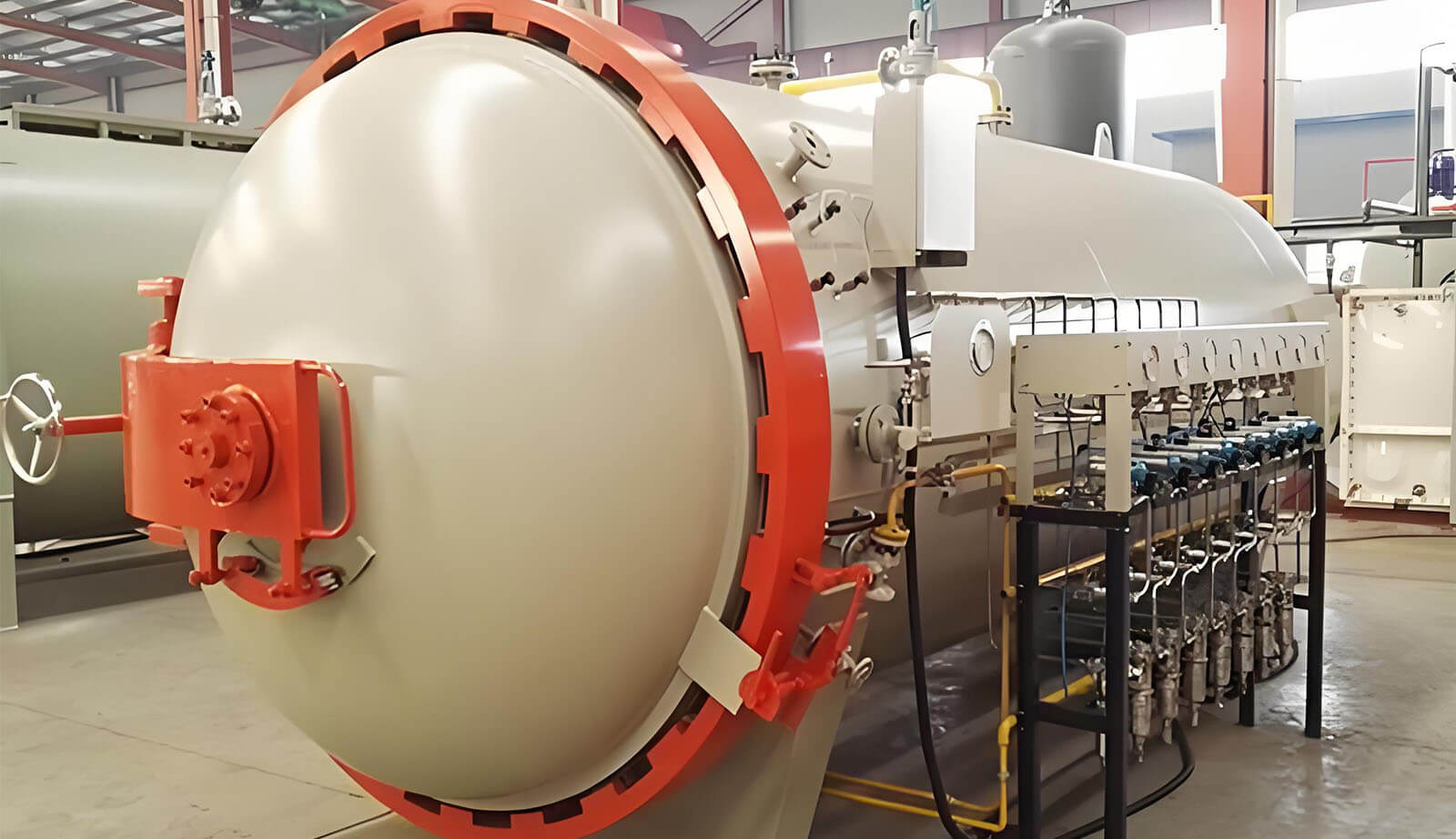
우리 공장은 100개 이상의 핫 압력 오토클레이브를 운영하며, 탄소 섬유를 정밀하게 형성하기 위해 알루미늄 몰드와 진공 유도 방식을 사용합니다. 고온과 압력이 강도, 안정성 및 완벽한 품질을 향상시킵니다.
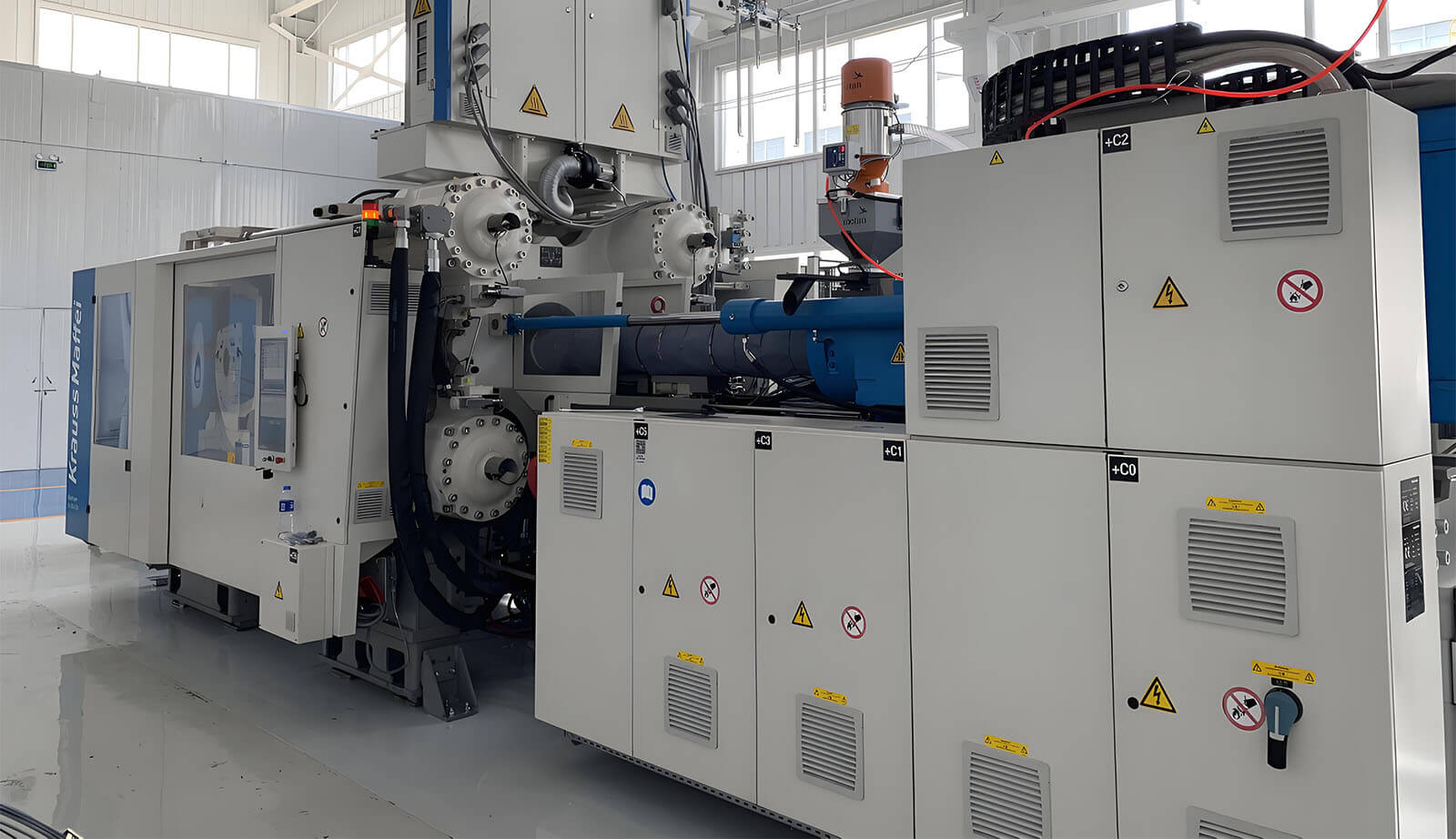
우리 탄소 섬유 연구 센터는 첨단 복합재료와 크라우스 마페이 파이버폼을 사용하여 새로운 에너지, 지능 및 경량 설계에서 혁신을 주도하며, 고객 중심 솔루션을 창출합니다.
경험이 풍부한 탄소 섬유 제품 공장에서 자주 묻는 질문에 대한 답변입니다.
우리는 자동차 부품, 오토바이 부품, 항공 우주 부품, 해양 액세서리, 스포츠 장비 및 산업 용도를 포함한 다양한 카본 파이버 구성 요소를 생산합니다.
우리는 주로 고품질 프리프레그 카본 파이버와 대형 카본 파이버 강화 고성능 복합재를 사용하여 강도, 내구성 및 경량 특성을 보장합니다.
네, 우리의 제품은 UV 보호 마감 처리되어 장기간 내구성을 보장하고 광택 있는 외관을 유지합니다.
네, 우리의 시설과 장비는 정밀도와 품질을 유지하면서 대형 카본 파이버 구성 요소를 생산할 수 있습니다.
카본 파이버 제품을 사용하면 어떤 이점이 있나요?
카본 파이버는 뛰어난 강도 대 중량 비율, 부식 저항, 강성, 열적 안정성 및 세련되고 현대적인 외관을 제공합니다.
우리는 경량 및 고성능 탄소 섬유 구성 요소에 중점을 두고 자동차, 오토바이, 항공우주, 해양, 의료, 스포츠 및 산업 분야에 서비스를 제공합니다.
네, 우리는 제공 맞춤형 탄소 섬유 독특한 디자인, 크기 및 패턴을 포함하여 사용자 요구 사항에 맞춘 솔루션을 제공합니다.
우리는 오토클레이브 성형, 핫 프레싱 및 진공 포장과 같은 첨단 기술을 활용하여 모든 제품에서 정밀도, 안정성 및 품질을 보장합니다. Hello Elementor 테마로 멋진 경험을 제공하기 위해 모든 주요 테마와 잘 작동하도록 노력하고 있습니다.
우리는 복잡하고 정밀한 탄소 섬유 구성 요소를 생성하기 위해 내구성과 높은 정확성을 위해 설계된 알루미늄 및 P20 강철 몰드를 사용합니다.
우리 제품은 치수 정확성, 재료 무결성 및 성능 테스트를 포함한 엄격한 품질 관리 검사를 거쳐 산업 표준을 충족합니다.