Specifications for Drilling Holes in Carbon Fiber Composite Materials
Abstract
Carbon fibre-reinforced polymer (CFRP) composites have become essential in high-performance industries such as aerospace, automotive and high-end sporting goods, owing to their exceptional strength‐to‐weight ratio, stiffness and fatigue resistance. Yet, drilling high-quality holes in CFRP laminates remains a significant manufacturing challenge due to anisotropy, heterogeneity and the contrasting behaviour of carbon fibres and polymer matrix. Hole quality is critical — defects such as delamination, burrs, fiber pull-out and thermal degradation can compromise structural integrity, bolt or rivet fastening performance, fatigue life and part acceptance. This review article synthesises current knowledge on drilling mechanisms and thermo-mechanical responses in CFRP; explores drilling-induced damage types and their causes; details how process conditions (cutting speed, feed, tool geometry/materials, cooling environment) affect outcomes; and outlines best-practice approaches towards achieving high-quality holes with minimal damage. It culminates in practical specifications and industrial recommendations for drilling CFRP laminates, and identifies future research directions including sensorised drilling, and sustainable machining methods.
1. Introduction
The mounting demand for lightweight, high-performance structural components in aerospace, automotive and wind energy sectors has driven widespread adoption of carbon fibre-reinforced polymer (CFRP) composites. Their appealing combination of high specific modulus, high specific strength, corrosion resistance and fatigue performance has made them material of choice for fuselage panels, auto body sub-frames, marine structures and high-performance sporting goods, including structurally demanding products such as carbon fiber electric surfboards, where lightweight construction, stiffness, fatigue resistance and water exposure performance are simultaneously required. Yet, successful integration of CFRP components in assemblies typically requires mechanical fastening or adhesive bonding — which in turn demands precision-drilled holes that meet stringent tolerances for diameter, roundness, surface finish and absence of internal damage.
Despite the maturity of composite manufacturing in terms of lay-up, curing and finishing, the drilling operation remains a weak link: compared to homogeneous metallic alloys, laminates such as CFRP exhibit pronounced anisotropy (due to fibre orientation), heterogeneity (strong fibre vs weaker matrix), and radically different machinability behaviour (e.g., brittle fracture dominated removal rather than ductile chip formation). Consequently, drilling often introduces defects—most notably delamination at entrance or exit surfaces, burrs, fibre pull-out or tearing, and thermal damage to the resin matrix.
Existing literature (for example the comprehensive review by Xu et al. “A review on CFRP drilling: fundamental mechanisms, damage issues and approaches toward high-quality drilling”) indicates that despite decades of research there is no single “universal” drilling specification for all CFRP stackups due to variation in fibre architecture, stacking sequences, resin system, tool geometry and cutting conditions.
The purpose of this article is to collate, synthesise and extend the state-of-the-art knowledge into a practical, specification-oriented guide: we review the fundamental mechanisms and responses, list damage modes and their controlling factors, explore process parameter influences, and provide actionable approaches and industrial recommendations for high-quality drilling.
In production environments, implementing these drilling specifications often requires production-ready CFRP machining support that integrates tooling selection, fixturing, inspection, and repeatable process control.
2. Drilling Mechanisms and Thermo-Mechanical Responses
To specify drilling parameters and tool requirements for CFRP, it is essential to understand the mechanisms at play during material removal, the resultant forces and torque behaviour, and the thermal field evolution during the process.
2.1. Drilling Mechanisms
Unlike homogeneous metals where continuous chips form via plastic deformation, CFRP removal is dominated by brittle fracture of fibres and shearing or crushing of the resin matrix. The fibre–matrix heterogeneity means that the tool edge alternately interacts with very stiff carbon fibres (high modulus, brittle) and much softer polymer resin (ductile or visco-elastic), and the removal mechanism often involves compression, bending and shearing of fibres, interfacial debonding, and matrix cracking.
In drilling, the rotating helix tool produces a helical path: the primary mechanisms include high thrust force (which can cause bending of laminate plies), tool–work interface sliding (producing friction and heat), fibre rupture ahead of the tool and matrix shear behind the tool. If support is insufficient, the bottom ply may deflect, causing “peel-up” delamination at the entrance or “push-down” delamination at the exit.
Specifically, chip formation in CFRP tends to be short, discontinuous fragments rather than long continuous ribbons; the tool contact length is short and crater wear of the tool is less dominant than abrasion wear. Understanding these mechanisms is key to setting tool geometry (e.g., point angle, chisel edge thinning) and selecting support/backing strategies.
2.2. Drilling Forces
The drilling process generates two primary mechanical responses: axial thrust (or thrust force) and torque. The magnitude of thrust is strongly correlated with feed rate and tool point geometry: higher feed increases the uncut chip volume per revolution, hence a larger thrust force which may exceed the interlaminar bond strength and initiate delamination. For CFRP laminates, even modest thrust can initiate inter-laminar separation if support is weak.
Research has shown that for CFRP drilling, maintaining low feed rate (thus lower thrust) is beneficial to hole quality. Xu et al. reported that high cutting speeds and low feed rates improved hole quality. Additionally, tool design affects thrust: a step drill or brad point drill tends to reduce thrust compared to a conventional twist drill.
Torque is also pertinent: torque trends indicate tool engagement with fibre–matrix, and excessive torque may reflect tool wear, fibre build-up or resin smearing. Monitoring torque is useful for process control and can serve as a proxy for impending damage or tool failure.
2.3. Cutting Temperatures
Because CFRP has low thermal conductivity (particularly transverse to fibre orientation) and dissimilar temperatures between fibre and resin phases, heat generated at tool–work interface tends to accumulate locally, raising temperatures in the vicinity of the hole wall and possibly degrading the resin. Elevated temperatures can cause matrix softening, resin char, fibre–matrix debonding or scorch, and subsequent reduction in structural performance of the hole.
While temperatures in CFRP drilling are often lower than in metal drilling due to brittle fracture dominating removal (less plastic deformation, less heat generation), the localized heating still matters, especially in deep holes or high-speed drilling. Cooling methods (cryogenic CO₂, MQL, or internal coolant) can help manage thermal damage.
For example, simulation studies show that increasing cutting speed reduces fibre deformation, matrix cracking and extension of damage zones, partly because higher speeds reduce the time for heat accumulation. Engineers must consider thermal field when specifying drilling for CFRP: tool coatings with high thermal conductivity (e.g., diamond, PCD) and cooling strategies become part of the specification.
3. Drilling-Induced Damages
Even when machining conditions are carefully controlled, drilling CFRP may yield quality-reducing defects. Understanding these damage types, their causation and detection is vital for specifying acceptable tolerances and inspection regimes.
3.1. Delamination
Delamination is arguably the most critical defect in drilling CFRP. It represents the separation of one or more plies at the entry (peel-up) or exit (push-down) of the drill hole. Delamination severely degrades the mechanical performance (tensile, compression and fatigue) of the drilled laminate and often results in part rejection.
Peel-up occurs during tool entry when the chisel edge lifts the laminate plies instead of shearing cleanly. Push-down happens at the exit when the drill thrust plus backing plate deflection allows the bottom ply to bend downward and separate.
Factors contributing to delamination include: excessive thrust force, inadequate backing support, dull or worn tool, inappropriate point angle, high feed rates, poor stacking sequence and lack of backup plate. Analytical and experimental models (Krishnamoorthy et al.) show that when the thrust force exceeds a critical threshold (dependent on inter-laminar strength), delamination initiates. Quantitative metrics such as the delamination factor (ratio of delaminated area to nominal hole area) are widely used.
3.2. Burrs
Burrs, especially exit burrs, are extraneous resin/fibre protrusions around the hole edge, typically more prevalent when drilling CFRP/metal stacks (for example CFRP/Ti). Burrs create stress-concentrations, compromise fastener seating and reduce fatigue life. Burr formation is associated with fibre pull-out, tool exit condition and stack interface behaviour. The use of appropriate backing support and low thrust helps reduce burr height.
3.3. Tearing and Fibre Pull-Out
Tearing refers to fibre breakage or pull-out at the hole wall surface, leading to rough, uneven hole surfaces. This can happen when tool geometry is not optimised for composite machining (e.g., point angle too steep, helix angle low), or when the resin matrix has softened (due to heat) resulting in weak fibre–matrix support. Rapid tool wear exacerbates this defect because the edge radius increases, promoting fibre dragging rather than clean shearing. Tearing leads to increased surface roughness, reduced fastener bearing area and may necessitate rework or removal of the hole.
3.4. Surface Cavities and Matrix Cracks
Surface cavities refer to small voids or missing resin zones around fibre bundles near the hole walls. These often originate from excessive heat, resin softening or inappropriate tool geometry (which may cause resin smearing or recession). Matrix cracking emanates from the drilling action – either from brittle fracture of the resin or from high interfacial strain between fibre and matrix. Both cavities and cracks degrade compressive, shear and bearing strength of the region adjacent to the drilled hole, and may affect adhesive bonding or fastener seating.
These damage types must be considered when specifying acceptable hole quality criteria, inspection thresholds, and rework protocols in industrial manufacturing.
4. Effects of Process Conditions
The quality of drilled holes in CFRP is strongly governed by a set of process parameters, tool characteristics and machining environment. Below we detail how each of these factors influences results and what specification ranges or considerations should apply.
4.1. Drilling Parameters
Cutting speed (Vc): For CFRP laminates, typical cutting speeds range from ~30 m/min to 120 m/min depending on tool material, laminate thickness and diameter. Several reviews report that higher cutting speeds (within tool life limits) tend to reduce thrust and delamination because they reduce the time for bending of plies and reduce chip accumulation. However, very high speeds may exacerbate tool wear or generate thermal damage, so tool-life limits must be considered.
Feed rate (f): Feed per revolution (mm/rev) is arguably the most critical parameter for drilling CFRP. Lower feed reduces uncut chip volume per revolution, which lowers thrust force and reduces risk of delamination. Typical feeds in research are in the range of 0.01 mm/rev to 0.10 mm/rev, with the lower end preferred for high-quality holes. In industrial settings for aerospace, feed may be tighter (e.g., 0.02-0.05 mm/rev) depending on diameter and laminate thickness.
Hole diameter tolerance and finish: In aerospace CFRP drilling, diameter tolerance is often ±0.05 mm or finer, roundness within 0.01 mm, and surface roughness (Ra) in the range of 1–3 µm. While these targets are not always published, they are implied by assembly specifications. The feed and speed must be selected such that these tolerances are achievable given the laminate thickness, fibre orientation and tool wear.
Stack configuration and fibre orientation: The stacking sequence and fibre orientation influence drilling behaviour significantly. For example, unidirectional (UD) laminates vs quasi-isotropic stacks respond differently; holes drilled through plies with fibre orientations at 0°, 45°, 90° may yield different damage zones. Engineers must factor this into specifications — for example, drilling through ±45° plies may require lower tool feed or different tool geometry.
4.2. Cutting Tools
Tool material and coating: For drilling CFRP, tool materials such as high-speed steel (HSS) may suffice for occasional holes, but for production aerospace use, carbide or polycrystalline diamond (PCD) tools are preferred thanks to better wear resistance against abrasive carbon fibres. A dedicated review on tool wear in CFRP drilling emphasises that abrasion (carbon fibres acting as micro-grinding elements) is the predominant wear mechanism on drill edges. Therefore, specification should favour PCD or diamond-coated drills where throughput is high.
Tool geometry: Several geometric features influence performance:
- Point angle (or included angle): A typical twist drill point angle for metals (118°) is often too steep for composites. Point angles of ~90° to 140° have been studied; a larger point angle reduces thrust.
- Helix angle: A helix angle between ~20°–40° is commonly used. Higher helix angles facilitate chip evacuation but may increase thrust; lower helix angles reduce lifting forces.
- Chisel edge reduction / thinning of chisel zone: Minimising the chisel edge helps reduce thrust and peel-up delamination.
- Step drill, brad point or dagger drills: Special geometries offer better control of entry forces and reduce damage. For example, step drills produce lower thrust and lower delamination factor compared to standard twist drills.
Tool wear and life: Because carbon fibres are highly abrasive, tool wear is accelerated in CFRP drilling. Worn tools produce increased thrust and torque, thus increasing risk of damage. The specification should include tool life limits (e.g., maximum number of holes, wear measurement threshold) and tool monitoring strategy (e.g., edge radius measurement, torque trend monitoring). The review by Xu et al. underscores the absence of comprehensive models linking tool wear progression to damage in CFRP drilling — but nevertheless warns that tool wear is a key parameter for specification.
4.3. Cutting Environments
Dry vs lubrication vs cooling: Traditional drilling of composites often uses dry machining to avoid contamination of resin or adhesive bonding surfaces. However, owing to heat buildup and dust generation, alternative environments are specified. Cryogenic CO₂ cooling or cryogenic nitrogen has been explored to reduce thrust and temperature and improve hole quality. MQL (Minimum Quantity Lubrication) with biodegradable oils is another option, particularly where environmental and workplace health considerations apply. The specification should indicate which environment is permissible, and what cleanup / dust extraction measures are required.
Dust extraction and health & safety: Carbon fibre dust is electrically conductive and potentially hazardous (respirable, abrasive). Specification must include adequate extraction systems, containment, operator protection (respirator, gloves, eye protection) and disposal of cuttings. Also, tool and machine surfaces must be grounded to mitigate electrostatic discharge risk in aerospace environments.
Backing support/Fixturing: Proper backing support is critical to minimize exit delamination and burrs. Specification must enforce the use of a hardened backing plate or sacrificial insert beneath the laminate, with minimal gap (~0.1 mm) and clamping torque sufficient to prevent sheet movement. Vacuum fixturing may also be used for thin laminates. The backup must be aligned and at least one diameter larger than the drill clearance to ensure uniform support.
5. Approaches to Achieving High-Quality Drilling
Having established mechanisms, damage types and parameter influences, we now turn to specific approaches and best practices that an engineer should embed in specifications to achieve high-quality holes in CFRP.
5.1. Optimization of Drilling Parameters
Parameter optimisation should be based on multi-objective goals: minimise thrust and delamination, minimise surface roughness, control hole diameter and circularity, and maintain acceptable tool life. Statistical methods (Taguchi, Response Surface Methodology) and predictive models (regression, machine-learning) have been developed to identify optimal windows. For example, Fard et al. developed a PLS regression model to predict delamination factor in CFRP drilling with ~99.6% accuracy.
Key recommendations:
- Use moderate to high spindle speeds and low feed per revolution as a starting point (e.g., 5000 rpm for small diameters, feed ~0.02 mm/rev)
- Monitor thrust force and torque; if thrust rises sharply, reduce feed or tool should be replaced
- Validate hole quality via non‐destructive methods (ultrasonic, dye penetrant, eddy current) and correlate to process parameters
- Maintain a parameter matrix tailored to laminate thickness, diameter and fiber orientation
5.2. Appropriate Selection of Tool Geometries
Tool geometry selection is an integral part of specifications. Best practice includes:
- Use step drill or brad point geometry for critical holes to reduce thrust and peel-up delamination
- Consider point angle around 90°–120°, helix angle ~25°–35°
- Use drills with internal coolant or through-coolant when permitted (for high throughput)
- Specify tool diameters and tolerances consistent with hole diameter plus finishing allowance (~0.1 mm oversize) to allow reaming or hone afterwards
- Select tool coatings and edge treatments (e.g., honed edges, micro-features) for enhanced fibre cutting
5.3. Appropriate Selection of Tool Coatings
Because carbon fibres are extremely abrasive, tool coatings play a major role in extending tool life, maintaining edge sharpness and controlling heat. Specification should stipulate:
- For high‐volume or critical holes: PCD (polycrystalline diamond) or diamond‐coated carbide tools
- For moderate volume: carbide with nano‐diamond or TiAlN coatings
- Coating adhesion, thermal conductivity and wear resistance should be defined (e.g., flank wear VB ≤ 0.2 mm after 100 holes)
- Tools should be re-qualified after a fixed number of holes or when torque rise exceeds threshold
5.4. Advanced Drilling Techniques
Beyond conventional drilling, emerging methods are becoming specification-worthy for high‐quality or difficult stack configurations:
- Laser-assisted drilling: Hybrid laser-mechanical removal of CFRP offers minimal delamination and high throughput. Research shows reduced fibre pull-out and improved surface integrity.
- Ultrasonic-assisted drilling (UAD): Superimposes vibration (~20-30 kHz) on drilling to reduce thrust and improve chip evacuation.
- Water-jet-guided nanosecond laser drilling: Particularly for thin or delicate laminates, this method yields virtually damage‐free holes and excellent edge quality.
- Cryogenic CO₂ drilling / chilled coolant drilling: Lowers tool-work temperature, reduces matrix softening and improves hole quality in thick laminates. Each of these techniques may increase equipment and process cost, so specification should include cost-benefit analysis, machine capability requirements and operator training as part of the spec.
6. Concluding Remarks and Future Perspectives
This comprehensive review and specification-oriented article has outlined the key mechanisms governing drilling in CFRP composites, the damage modes that must be mitigated, the process condition effects and the implements available to achieve high-quality holes. From these insights we can draw several concluding remarks:
- Specification ranges: For many aerospace CFRP laminates, a safe starting point is high spindle speed and low feed (e.g., 60 m/min, 0.02–0.04 mm/rev) combined with well backed-up fixturing, PCD tools, and dust extraction.
- Tool and process monitoring: Monitoring thrust, torque, temperature and tool wear provides early warning of damage onset or tool life exceedance. These metrics should be written into the specification.
- Balance productivity and quality: While low feed and moderate speed yield best hole quality, production demands may require compromises — but these must be justified by testing and correlation to assembly performance.
- Emerging trends: Smart drilling with in-process sensing, AI-based adaptive control, real-time inspection of hole integrity and closed-loop parameter adjustment is the future. Sustainability is also key: dry or MQL machining, biodegradable lubricants, and controlled composite waste management will be part of the next-generation specification.
Future research directions should include:
- Developing comprehensive tool‐wear models that correlate wear progression with delamination, surface roughness and hole tolerances.
- Sensor-embedded drills that measure local temperature, force and vibration in real time for adaptive control.
- Standardised testing methods for advanced drilling techniques (laser-assisted, ultrasonic) applied to CFRP and CFRP/metal stacks.
- Life-cycle and environmental assessments of composite drilling operations (tool consumption, dust management, energy use) to aid sustainable specification development.
By encoding these insights into formal drilling specifications, manufacturers of CFRP components can improve reliability, reduce scrap and enhance assembly integrity — thereby unlocking the full potential of carbon fibre composites in demanding structural applications.
Table 1 — Recommended drilling parameters for CFRP by hole size & tool (production-grade)
Assumptions: Unidirectional or quasi-isotropic CFRP, room temp, dry/CO₂/MQL per column, laminate 3–8 mm, through-hole. Formula used: RPM = (Vc·1000)/(π·D). Always validate in trials.
| Hole Ø (mm) | Tool Material | Preferred Geometry | Cutting Speed Vc (m/min) | Example RPM | Feed per Rev (mm/rev) | Peck Cycle | Backing Support | Cooling / Extraction | Typical Use Case |
|---|---|---|---|---|---|---|---|---|---|
| 3 | PCD or diamond-coated carbide | Step or brad-point, chisel-edge thinned, helix 25–35° | 60–120 | 6,366–12,732 | 0.010–0.030 | Light (every 0.5–1 mm) | Steel/aluminum plate, gap ≤0.1 mm | Dry + vacuum or CO₂ | Rivet pilot holes, aerospace clips |
| 3 | Micro-grain carbide (TiAlN/DLC) | Step or dagger | 40–80 | 4,244–8,488 | 0.010–0.020 | Light | Same as above | Dry or MQL | General fixtures, low volume |
| 6 | PCD or diamond-coated carbide | Step or brad-point | 60–100 | 3,183–5,305 | 0.020–0.050 | Moderate (every 1–2 mm) | Backing plate mandatory | Dry + vacuum or CO₂ | Structural fasteners |
| 6 | Carbide (DLC/TiAlN) | Step or dagger | 40–80 | 2,122–4,244 | 0.020–0.040 | Moderate | Backing plate mandatory | Dry / MQL | Automotive body, medium volume |
| 10 | PCD or diamond-coated carbide | Step with pilot | 60–100 | 1,910–3,183 | 0.030–0.080 | Moderate–heavy (every 1–2 mm) | Backing + clamp torque control | CO₂ or MQL preferred | Thick stacks, boss holes |
| 10 | Carbide (DLC) | Step or brad-point | 40–80 | 1,273–2,546 | 0.030–0.060 | Moderate–heavy | Backing + clamp torque control | Dry / MQL | General assembly |
Notes
- For CFRP/Ti stacks, pre-drill CFRP with step drill, then finish through Ti with coolant; consider orbital or peck-ream to control burrs.
- Start at the low end of feed; increase until thrust begins to rise; then step back.
- Replace tools when torque or thrust trends exceed baseline by ~15–20%.
Table 2 — Tool geometry, pros/cons & when to use
| Geometry | What it looks like | Pros in CFRP | Cons / Risks | Best for |
|---|---|---|---|---|
| Step drill | Two diameters, pilot then full | Low thrust, excellent exit quality | Needs precise alignment; cost | Most structural holes, exit delam control |
| Brad-point | Center spur with outer spurs | Clean entry, accurate location | Can raise exit thrust if no backing | Thin laminates, cosmetic surfaces |
| Dagger / “candle-stick” | Long thin pilot, minimal chisel | Very low thrust, crisp wall | Slower, fragile pilot | Precision holes, small Ø (≤6 mm) |
| Twist drill (thinned chisel) | Standard with web-thinning | Readily available | Higher thrust vs. step/brad | Non-critical holes, secondary ops |
| PCD-tipped | Polycrystalline diamond edges | Long life, low wear, clean wall | Cost; sensitive to runout | Production runs, aerospace |
| Diamond-coated carbide | CVD/diamond DLC on carbide | Great wear resistance | Coating adhesion matters | Medium-to-high volume |
Table 3 — Inspection & acceptance (hole quality)
| Attribute | Method | Spec / Target (typical) | Action if Out of Spec |
|---|---|---|---|
| Diameter | Go/No-Go pin, bore gauge | ±0.05 mm (aero typical), ±0.10 mm (auto) | Adjust feed/RPM; new tool; re-drill/ream |
| Roundness | Bore gauge / CMM | ≤0.01–0.03 mm | Check runout/fixturing |
| Surface roughness (Ra) | Profilometer | 1–3 µm | Replace tool; reduce feed; CO₂/MQL |
| Entry/Exit delamination factor (Fd) | Visual + image analysis | Fd ≤ 1.2 (typical internal), ≤1.1 (critical) | Lower feed; improve backing; change geometry |
| Fibre pull-out / tearing | Stereo microscope / SEM spot checks | Minimal, no loose fibres | New tool; switch to step/brad |
| Heat damage / resin char | Visual/microscope | None visible; no discoloration | Lower RPM or add CO₂/MQL |
| Burr height (stacks) | Feeler/visual | ≤0.05 mm or per OEM | Deburr; alter sequence; coolant in metal |
Table 4 — Defects → root causes → fixes (quick troubleshooting)
| Defect | Likely Cause | Fix Fast | Fix Permanent |
|---|---|---|---|
| Exit delamination | Excess thrust, poor backing | Reduce feed; add sacrificial plate | Switch to step drill; revise clamp/torque |
| Entry peel-up | Large chisel edge, low point sharpness | Use pilot; thin chisel | Brad-point geometry; PCD |
| Fibre pull-out | Worn tool, too low helix | New tool; clean dust | Diamond-coated/PCD; optimize helix |
| Matrix burn/char | Too high temp; dull tool | CO₂/MQL; new tool | Lower RPM or intermittent cut |
| Oversize/ovality | Runout, flexible setup | Re-clamp; check spindle | Precision collet; shorter tool |
| Burrs in stacks | Wrong sequence, no coolant in metal | Deburr; peck | Orbital drilling; two-step process |
Table 5 — Safety & environmental controls
| Risk | Control | Spec |
|---|---|---|
| Carbon dust (respirable, conductive) | LEV extraction + HEPA | Capture ≥99% sub-5 µm; nozzle near tool |
| Operator exposure | PPE | P3/N100 mask, gloves, goggles |
| Static discharge | Grounding | Bond machine/extractor to earth |
| Waste | Segregation | CFRP swarf in sealed bags; label conductive |
Table 6 — DOE starter matrix (Taguchi L9) for CFRP drilling optimization
| Trial | Vc (m/min) | Feed (mm/rev) | Geometry | Cooling | Responses to record |
|---|---|---|---|---|---|
| 1 | 40 | 0.02 | Step | Dry | Thrust, torque, Fd, Ra, Ø |
| 2 | 40 | 0.04 | Brad | CO₂ | … |
| 3 | 40 | 0.06 | Thinned twist | MQL | … |
| 4 | 80 | 0.02 | Brad | MQL | … |
| 5 | 80 | 0.04 | Thinned twist | Dry | … |
| 6 | 80 | 0.06 | Step | CO₂ | … |
| 7 | 120 | 0.02 | Thinned twist | CO₂ | … |
| 8 | 120 | 0.04 | Step | MQL | … |
| 9 | 120 | 0.06 | Brad | Dry | … |
Tip: Optimise for min thrust & Fd with constraints on Ra and Ø tolerance, then verify tool life.
Quick figures
Figure 1 — Delamination types
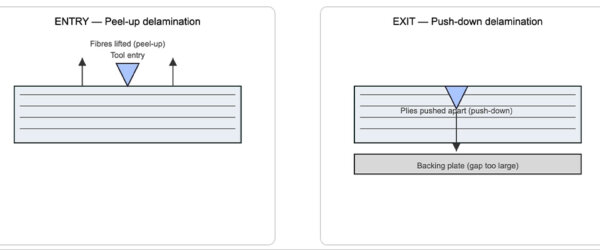
Figure 2 — Correct backing & clamping
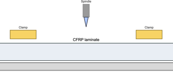
Figure 3 — Peck cycle guidance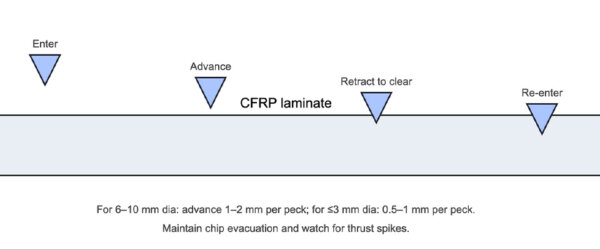
Declaration of Competing Interest
The author declares that no conflict of interest exists in the preparation of this article.
Acknowledgments
The author gratefully acknowledges the open literature reviews by Xu et al., and the contributions of manufacturing research communities in composite drilling who have advanced understanding of CFRP machining. (No external funding or specific industrial confidentiality was involved.)
About the author: Simon Lee has over 29 years of experience managing composite manufacturing supply chains for European OEMs and runs Chinacarbonfibers, a company specialising in custom carbon fibre products for aerospace, automotive, motorcycle, sports, medical, new energy, and custom racing carbon fibre reinforced plastic parts, with facilities including prepreg dry carbon, autoclave curing and 5-axis CNC finishing.
References
- Xu, J., et al. “A review on CFRP drilling: fundamental mechanisms, damage issues and approaches toward high-quality drilling.” Journal of Materials Research and Technology. 2023.
- Xu, J., “A review on tool wear issues in drilling CFRP laminates.” Frontiers in Materials. 2022.
- Patel, P., “Delamination evaluation in drilling of composite materials.” Journal of Manufacturing Processes. 2022.
- Fard, M. G., Baseri, H., Azami, A., Zolfaghari, A., “Prediction of Delamination Defects in Drilling of Carbon Fiber Reinforced Polymers Using a Regression-Based Approach.” Machines. 2024.
- Jagadeesh, P., et al. “Drilling characteristics and properties analysis of fibre composites.” PMC. 2023.
- Krishnamoorthy, A., et al. “Delamination Analysis in Drilling of CFRP Composites.” J. of Materials Processing Technology. 2009.
- Additional composite drilling reviews, “Holistic review of drilling on CFRP composites: Techniques, FEM, sustainability, challenges and advances.” 2025.

