
Industrial Carbon Fiber Parts Manufacturer
Custom CFRP components and composite parts for robotics, UAVs, automation equipment and industrial applications — OEM/ODM manufacturing from Suzhou, China.

Who This Page Is For
This page covers our custom industrial and advanced technology carbon fiber manufacturing capability — not automotive styling parts, not consumer accessories.
If you are an engineer, product developer, equipment manufacturer, robotics company, drone builder, OEM buyer or procurement manager looking for functional, load-bearing, dimensionally accurate carbon fiber composite parts, you are in the right place.
We work with customers who bring STEP/STP files, 2D engineering drawings, original samples, DXF cutting files, 3D scan data or project briefs. Our engineering team reviews part geometry, fiber direction, laminate structure, wall thickness, bonding interfaces, insert positions, tolerances and production process before any mold or tooling is built.
We have supplied carbon fiber components to robotics integrators, industrial automation equipment manufacturers, professional UAV and drone developers, energy project developers and precision instrument companies across Europe, North America, Japan and other markets worldwide.
If your project involves automotive carbon fiber body parts, we cover those separately under Carbon Fiber Car and Carbon Fiber Motorcycle. For the full range of custom composite applications — consumer, lifestyle, sports and industrial — see our Custom Carbon Fiber overview.
What Makes Industrial Carbon Fiber Different
Industrial carbon fiber components are not the same as cosmetic carbon fiber trim used in carbon fiber car body kits or carbon fiber motorcycle fairings. The differences matter, and misunderstanding them leads to parts that fail or underperform.
| Parameter | Industrial / Structural | Cosmetic / Automotive |
|---|---|---|
| Primary requirement | Stiffness, accuracy, repeatability | Surface appearance, weight reduction |
| Fiber orientation | Engineered per load direction (0°/45°/90°) | Often random or decorative |
| Laminate design | Load-specific, calculated ply stack | Standard schedule |
| Tolerances | ±0.1–0.3 mm on critical features | Looser, surface-focused |
| Insert design | Threaded metal inserts, bonding blocks | Rarely required |
| Surface finish | Functional (matte, satin, raw CF) | High-gloss cosmetic |
| QC focus | Dimensional, flatness, weight, fiber integrity | Visual surface inspection |
| Typical process | Prepreg + autoclave, infusion, filament winding | Wet layup, prepreg hand layup |
| Prototype review | Engineering feasibility required | Sample approval |
We have manufactured both. For industrial projects, we always recommend a design feasibility review before mold production — this step alone saves customers from costly tooling revisions.
Industrial Carbon Fiber Components We Manufacture
The following represents the range of custom industrial and advanced technology carbon fiber parts we produce. This is not a complete list — if your part type is not listed here, contact us with your drawings or samples.
Structural and Load-Bearing Components
- Carbon fiber beams (rectangular, square, custom section)
- Carbon fiber C-beams, U-channels and T-sections
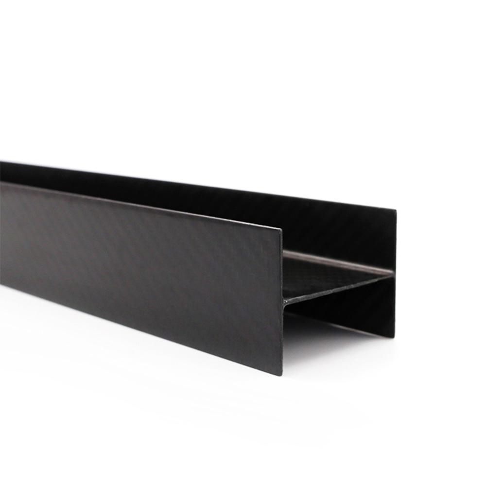
- Carbon fiber I-beams and structural profiles
- Carbon fiber strips and flat bar sections
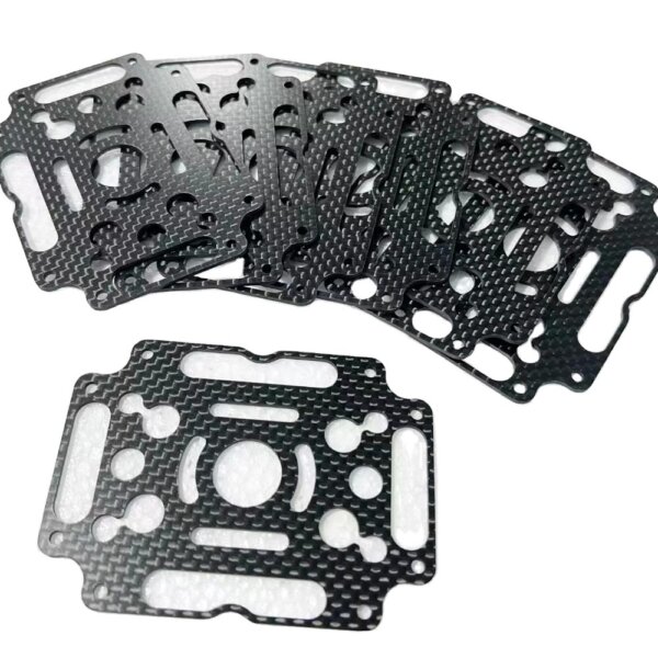
- Carbon fiber mounting plates and base plates
- Carbon fiber brackets and angle supports
- Carbon fiber stiffener ribs and gussets
- Carbon fiber honeycomb sandwich panels
- Carbon fiber foam-core sandwich panels
- Carbon fiber flat laminate sheets and plates
- Hybrid composite structures (carbon/fiberglass, carbon/aramid)
Robotics and Automation Parts
- Carbon fiber robotic arm links and lever sections
- Carbon fiber end-effector components
- Carbon fiber lightweight brackets and joint housings
- Carbon fiber linear slide support rails
- Carbon fiber machine vision system housings
- Carbon fiber inspection device frames
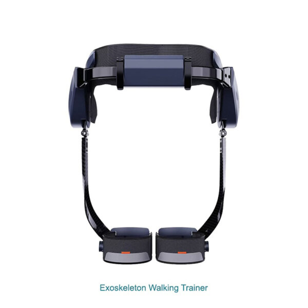
- Carbon fiber exoskeleton components and limb sections
- Carbon fiber sensor mounting plates
- Carbon fiber cable management profiles
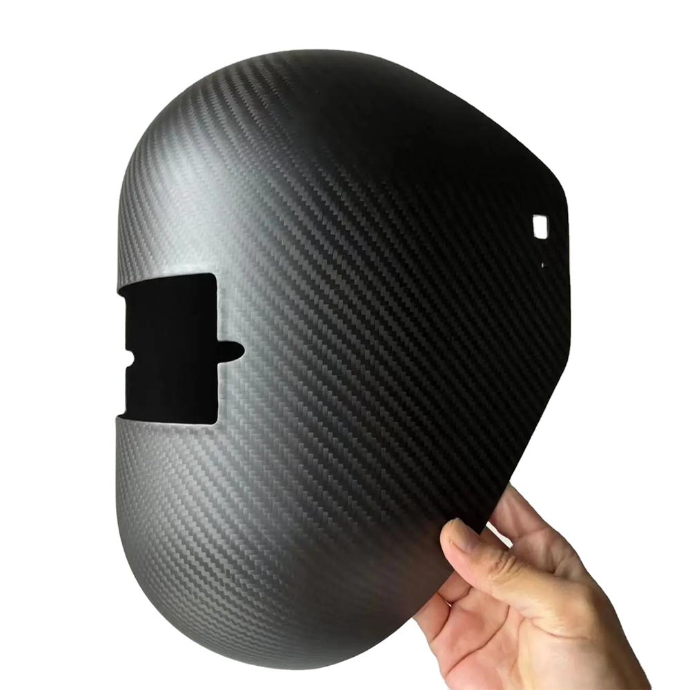
- Carbon fiber automation equipment covers and panels
Drone and UAV Components
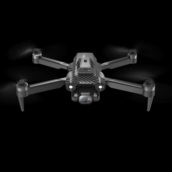
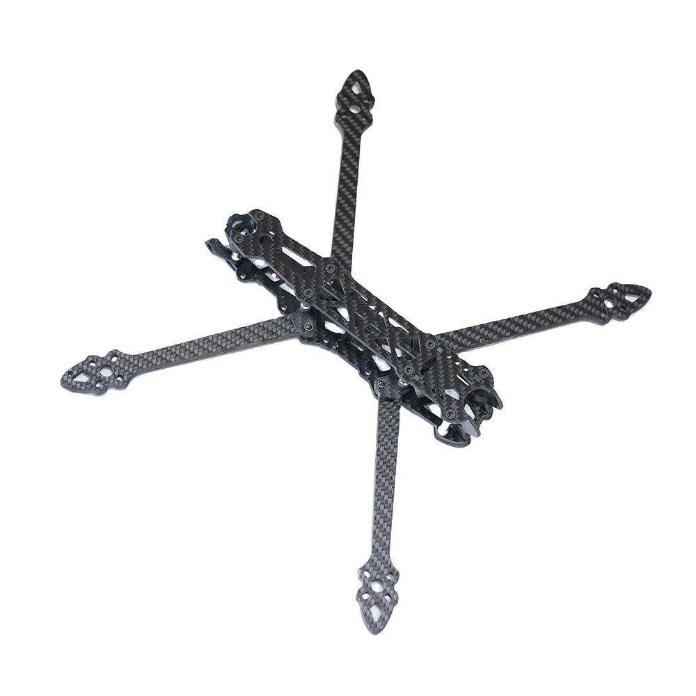
- Carbon fiber drone frames (quadcopter, hexacopter, fixed-wing)
- Carbon fiber UAV arm tubes and folding arm sections
- Carbon fiber payload mounting plates and gimbal boards
- Carbon fiber battery compartment covers and shells
- Carbon fiber antenna mounts and landing gear struts
- CNC-cut carbon fiber frame plates (from DXF files)
- Carbon fiber tube-and-plate UAV chassis assemblies
- Carbon fiber propeller guards and protective rings
- Filament-wound carbon fiber UAV boom tubes
- Carbon fiber VTOL transition frames and structural plates
Tubes, Rods and Profiles
- Roll-wrapped carbon fiber round tubes (custom OD, wall thickness, length)
- Filament-wound carbon fiber tubes (high hoop strength, pressure-rated designs)
- Pultruded carbon fiber rods and solid round sections
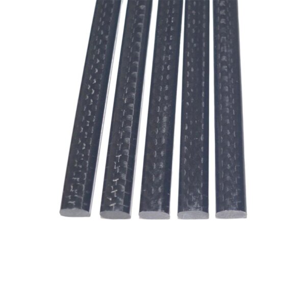
- Pultruded carbon fiber flat strips and rectangular profiles
- Pultruded carbon fiber channels, I-beams and custom sections
- Carbon fiber square tubes and multi-bore sections
- Telescoping carbon fiber tube sets for inspection and reach poles
Equipment Covers, Housings and Enclosures
- Carbon fiber machine covers and equipment guards
- Carbon fiber instrument housings and enclosures
- Carbon fiber portable equipment shells
- Carbon fiber medical-adjacent device covers and panels
- Carbon fiber electronics enclosures and protective cases
- Carbon fiber sensor covers and protective housings
- Carbon fiber inspection equipment shells
Precision and Specialty Parts
- CNC-cut carbon fiber flat parts (from DXF, STEP or 2D drawings)
- Carbon fiber jigs and fixture components
- Carbon fiber test bench frames and structural platforms
- Carbon fiber CT table panels and imaging equipment boards
- Carbon fiber tool handles and lightweight grips
- Carbon fiber lightweight structural prototypes
Energy and Infrastructure Components
- Carbon fiber solar panel mounting brackets and rail systems
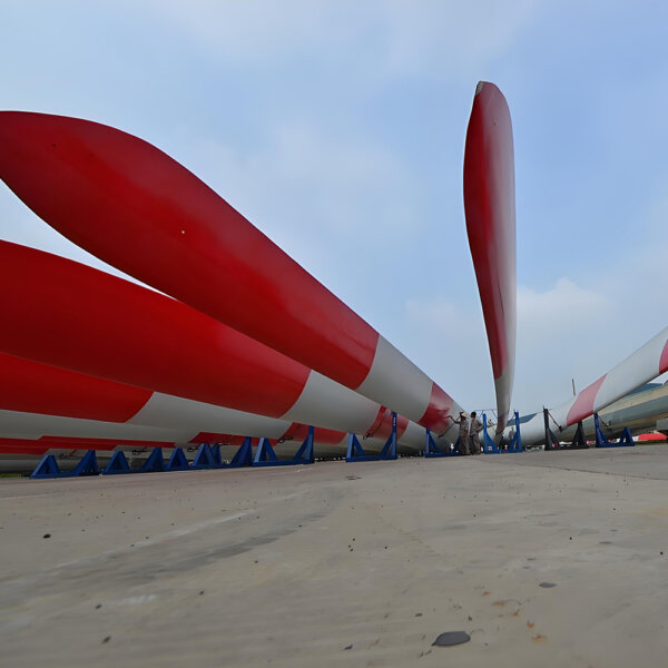
- Carbon fiber wind turbine blade reinforcement sections
- Carbon fiber wind power structural profiles and root components
- Carbon fiber corrosion-resistant panels for offshore applications
Materials We Work With
Material selection is one of the most important decisions in industrial carbon fiber part design. The right fiber grade, weave pattern, resin system and core material directly affects stiffness, surface quality, weight, cost and production repeatability. Industrial applications draw from the same material range as our broader custom carbon fiber manufacturing capability, but the selection criteria and laminate engineering are driven by function rather than appearance.
Carbon Fiber Fabric and Fiber Options
| Material | Grade / Spec | Weave / Form | Common Application |
|---|---|---|---|
| 3K carbon fiber | T300-equivalent standard modulus | 2×2 twill | Covers, housings, general structural parts |
| 3K carbon fiber | T300-equivalent | Plain weave | Precision plates, panels, fine surface finish |
| 6K carbon fiber | Standard modulus | 2×2 twill | Heavier structural panels, tooling skins |
| 12K carbon fiber | Standard modulus | Twill or plain | Thick structural parts, cost-sensitive panels |
| Unidirectional (UD) | T700-equivalent intermediate modulus | 0° or 90° tape | Beams, rods, high-stiffness laminate reinforcement |
| High-modulus UD | T800-equivalent high modulus | 0° tape | Stiffness-critical structures, UAV wings |
| Spread tow fabric | Ultra-flat | Balanced weave | Ultra-thin panels, aerodynamic skins |
| Carbon / fiberglass hybrid | — | Woven hybrid | Impact resistance + stiffness balance |
| Carbon / aramid hybrid | — | Woven hybrid | Impact resistance, UAV frames, protective parts |
We source fiber from major producers and select specification grades matched to project stiffness, strength and cost requirements. For projects with specific fiber grade requirements (Toray T300, T700, T800 or equivalent), please state this in your inquiry.
Prepreg vs. Dry Fiber Systems
Prepreg carbon fiber (resin pre-impregnated at controlled fiber-to-resin ratio) is our standard for industrial components requiring:
- Consistent fiber volume fraction (typically 55–65%)
- Predictable mechanical performance batch-to-batch
- Good laminate consolidation with low void content
- Better A-surface finish directly from the mold
- Stable laminate thickness and weight
Dry fiber with vacuum infusion or wet layup is used for:
- Larger parts where prepreg handling is impractical
- Cost-sensitive production where surface variation is acceptable
- Large covers, panels and housings where infusion cost-quality balance is suitable
For industrial structural components — robotic arms, drone frames, beams and stiffness-critical parts — prepreg with autoclave or press curing is generally recommended over wet layup. The suitability of each process should be reviewed based on geometry, load requirements and production volume.
Core Materials for Sandwich Panels
| Core Material | Density | Best For |
|---|---|---|
| Nomex honeycomb | Very low | High-performance lightweight panels, UAV boards, CT table panels |
| Aluminum honeycomb | Low | Structural panels, flat rigid surfaces |
| PMI foam (Rohacell-type) | Low–medium | Complex curved panels, thermoformed sandwich parts |
| PVC foam (Divinycell-type) | Low–medium | Marine, industrial covers, cost-effective sandwich panels |
| Balsa wood | Medium | Tooling skins, large flat panels |
Manufacturing Processes
The appropriate manufacturing process depends on part size, geometry, wall thickness, required tolerance, surface quality, production volume and laminate performance requirements.
Prepreg Hand Layup + Autoclave Curing
Best for: High-performance robotic parts, UAV structures, drone frames, precision panels and advanced composite components requiring consistent laminate quality.
Prepreg plies are cut and laid up in a mold according to an engineered ply schedule, vacuum bagged and cured in an autoclave at controlled temperature and pressure. This process generally delivers better fiber volume fraction, lower void content and tighter laminate consistency compared to wet layup — well-suited for demanding industrial applications where part-to-part repeatability is important.
Typical characteristics:
- Wall thickness: 0.5 mm to 8 mm+
- Fiber volume fraction: typically 55–65% (prepreg process)
- A-surface finish: higher consistency than wet layup
- Tolerances: ±0.1–0.2 mm on critical dimensions after CNC trimming (dependent on part geometry, mold quality and curing process)
Vacuum Infusion (VARTM)
Best for: Large equipment covers, panels, housings, frames and parts where size or cost makes prepreg processing impractical.
Dry fiber is positioned in the mold, sealed under vacuum, and resin is drawn through the laminate under atmospheric pressure differential. Well-suited for one-sided molds and medium-to-large industrial parts.
Typical characteristics:
- Wall thickness: 1.5 mm to 20 mm+
- Good A-surface quality; suitable for functional industrial finish
- Lower tooling and material cost than prepreg for large or low-volume parts
Wet Layup
Best for: Simple covers, non-structural housings, prototype verification parts and cost-sensitive components where surface consistency requirements are lower.
Dry fiber is impregnated by hand with liquid resin and consolidated under vacuum or atmospheric pressure. This is the most accessible process and is suitable for prototypes, low-volume parts and non-structural components. Surface consistency and fiber volume fraction are lower than prepreg or infusion.
Compression Molding (Press Molding)
Best for: Repeat production of medium-sized covers, brackets, shells and forged carbon fiber parts requiring consistent geometry and shorter cycle times.
Matched metal or composite tooling with press curing delivers consistent repeat parts with controlled thickness. Used for forged carbon fiber appearance and engineering-grade structural components in series production.
Filament Winding
Best for: Carbon fiber tubes, pressure vessels, cylindrical structures and rotationally symmetric parts requiring high hoop strength.
Continuous fiber tow is wound over a mandrel at precisely controlled fiber angles (helical, hoop or combination), then cured and demolded. Filament winding produces tubes and cylindrical parts with excellent controlled stiffness in specific directions.
- Fiber angle can be controlled from near 0° (axial) to 90° (hoop)
- Well-suited for UAV boom tubes, inspection poles, structural cylinders and pressure-rated tubes
- Custom diameter, wall thickness and length to specification
- Suitable for both carbon fiber and hybrid carbon/fiberglass tube designs
Roll-Wrapping (Tube Wrapping)
Best for: Custom round tubes and tapered tubes requiring specific OD, wall thickness and fiber angle. More flexible than pultrusion for low-to-medium volume production.
Prepreg plies are wrapped over a mandrel and cured, producing round tubes with controlled lay-up angle. Common for UAV boom arms, robotic link tubes, instrument poles and structural round section components.
Pultrusion
Best for: Continuous carbon fiber profiles — flat strips, rods, round tubes, rectangular tubes, channels and I-sections — requiring consistent section properties and high longitudinal stiffness.
Pultrusion pulls fiber continuously through a resin bath and heated die, producing sections with very high fiber volume fraction in the longitudinal direction. Well-suited for structural strips, flat bars, rods and standard profiles produced in consistent lengths.
RTM (Resin Transfer Molding)
Best for: Closed-mold production of structural components with good fiber content on both surfaces. Suitable for more complex-geometry parts in medium production volumes where two-sided surface quality is required.
Dry fiber preform is placed in a closed mold, resin is injected under pressure and cured. Compared to infusion, RTM offers better control over fiber placement and resin pressure. Used for structural covers, brackets and composite assemblies in repeat production.
CNC Machining of Carbon Fiber Plate, Sheet and Tube
Best for: Flat brackets, drone frame plates, mounting plates, strips, channels and custom-profiled parts — produced directly from carbon fiber sheet or tube stock without dedicated tooling.
We operate CNC routers and machining centers capable of:
- 2D profile cutting from DXF files
- Pocket milling and step features
- Drilling and countersinking (carbide tooling, dust extraction)
- Slotting, notching, tab and slot features
- Custom tube end profiling and mitering
CNC machining from existing plate stock offers the shortest lead time and lowest tooling cost for flat geometry parts. Tolerances on machined features depend on material thickness, geometry, clamping method and drawing requirements. Critical dimensions should be identified in drawings for process review before production.
Insert Integration, Bonding and Assembly
For industrial applications, most carbon fiber parts need to connect to metal structures, fastened assemblies or precision mechanisms. Composite-to-metal connections require careful design — thread engagement directly into carbon fiber is generally not recommended for structural fastener loads.
Options we support:
Threaded Metal Inserts
Aluminum, steel or stainless steel threaded inserts can be co-bonded during laminate curing or installed post-cure using structural adhesive. Inserts allow standard fastener connections without risk of crushing the laminate under clamp load.
Aluminum Reinforcement Blocks
For high-load fastener areas, aluminum blocks bonded or co-cured into the laminate provide a reliable load path. Common in drone arms, robotic joints and structural bracket assemblies where pull-out and bearing loads are significant.
Adhesive Bonding Interfaces
For parts requiring bonding to metal substructures, we can prepare bonding surfaces with specific texture, flatness and surface treatment to support structural adhesive joints (epoxy film adhesive, paste adhesive).
Multi-Part Assembly
Some industrial carbon fiber assemblies consist of multiple sub-components bonded, fastened or integrated with metal hardware. We can review assembly drawings and manage multi-part production as a single order, including insert installation, sub-assembly bonding and dimensional verification of the assembled unit.
Tolerances and Dimensional Expectations
Indicative tolerance expectations for carbon fiber composite parts. Actual results depend on part size, geometry, curing method, mold quality and material. Critical tolerance features must be identified in drawings before mold design begins.
| Feature Type | As-Molded | After CNC Trimming |
|---|---|---|
| Outer profile dimension | ±0.3–0.5 mm | ±0.1–0.2 mm |
| Wall thickness | ±0.1–0.2 mm | — |
| Flatness (per 300 mm span) | 0.3–0.8 mm | 0.1–0.3 mm |
| Hole diameter | — | ±0.05–0.15 mm (geometry and fixture dependent) |
| Hole center position | — | ±0.05–0.15 mm (geometry and fixture dependent) |
| Edge quality | Flash removal, deburred | Clean machined, deburred |
| Surface roughness (A-face, prepreg) | Ra 0.8–1.6 µm typical | — |
For projects with accuracy requirements tighter than these ranges, please discuss the specific critical features with us during the design review stage before tooling commitment.
Lead Times by Project Type
Lead time depends on part complexity, tooling requirements, production process and quantity. The following represents typical timelines under normal production loading.
| Project Type | Typical Lead Time | Notes |
|---|---|---|
| CNC-cut flat parts (from plate stock) | 5–10 business days | No tooling required; fastest option |
| First prototype — simple geometry | 3–4 weeks | Includes mold fabrication |
| First prototype — complex geometry | 4–6 weeks | Larger or multi-part mold |
| Sample approval revision | 1–2 weeks | After customer review |
| Small batch (5–50 pcs, after approval) | 2–3 weeks | Process confirmed |
| Repeat OEM/ODM production | Per agreed schedule | Based on order volume and capacity |
For urgent prototype requirements, please contact us with your drawings. We will confirm realistic timelines based on current workshop capacity before committing.
Quality Management and Inspection
Our quality inspection for industrial carbon fiber parts focuses on dimensional accuracy, laminate integrity and functional performance.
Our quality management process follows ISO 9001 principles across material sourcing, production process control, dimensional inspection and pre-shipment verification. For OEM/ODM customers with specific quality documentation requirements, inspection plans can be agreed before production starts.
Standard Inspection Items
Dimensional Inspection
- Overall outer dimensions vs. drawing (digital caliper, CMM for critical parts)
- Hole diameter and position
- Flatness and straightness (surface plate check)
- Wall thickness (ultrasonic gauge or cross-section)
- Insert position and thread engagement check
Laminate Quality
- A-surface void and pinhole inspection
- Delamination check (tap test; ultrasonic on request for structural parts)
- Fiber orientation review (visible layer check or cross-section sample)
- Weight check per batch (correlation to designed fiber volume)
Assembly and Function Check
- Fitment check with customer-supplied mating parts or gauges where provided
- Insert pull-out or torque test on request
- Edge quality and burr inspection after CNC machining
Documentation Available on Request
- Dimensional inspection report
- Weight and thickness record per batch
- Material certificate for prepreg or fabric lot
- Pre-shipment photographs (all shipments)
- Packing and export documentation
For OEM customers requiring specific inspection standards, material traceability, incoming inspection reports or custom documentation formats, please specify these requirements at the inquiry stage. Details of our production facility, equipment and inspection setup are available on our About page.
OEM/ODM Project Workflow
For new industrial carbon fiber projects, we follow a structured development process to minimize tooling revisions and production delays.
1. Inquiry & Design Review
   ↓ DFM feedback on geometry, wall thickness, fiber direction,
     draft angles, insert positions, tolerance feasibility

2. Material & Process Recommendation
   ↓ Fiber grade, weave, resin system, core material, process

3. Mold / Tooling Design & Fabrication
   ↓ Tooling material selected per volume, geometry,
     curing temperature requirement

4. Prototype / First Article Sample
   ↓ First physical parts, dimensional inspection,
     weight record, fitment check with mating parts

5. Customer Sample Approval
   ↓ Customer reviews, requests revisions if needed

6. Small Batch Production
   ↓ Process parameters confirmed, QC documented

7. Repeat OEM/ODM Manufacturing
   ↓ Consistent materials, process and inspection
     per approved first article reference
Approved first article samples serve as the production reference standard. Engineering changes after first article approval will trigger a review of mold, process and inspection plan impact before revised production proceeds.
Why Carbon Fiber for Industrial Applications?
Carbon fiber composites are selected when the combination of low mass, high stiffness, corrosion resistance and dimensional stability cannot be matched by aluminum, steel or engineering plastics at acceptable weight.
Indicative Performance Comparison
| Property | CFRP (UD Prepreg, ~60% Vf) | Aluminum 6061-T6 | Mild Steel | GFRP |
|---|---|---|---|---|
| Density (g/cm³) | ~1.55 | 2.70 | 7.85 | ~1.85 |
| Tensile strength (MPa) | ~1500 (0° direction) | ~276 | ~400 | ~300 |
| Tensile modulus (GPa) | ~130 (0° direction) | 69 | 200 | ~20 |
| Specific stiffness (E/ρ) | ~84 | ~26 | ~25 | ~11 |
| Corrosion resistance | Excellent | Good (anodized) | Poor | Excellent |
| CTE (10⁻⁶/°C) | ~0–2 (0° axis) | ~23 | ~12 | ~14 |
| Fatigue performance | Good | Moderate | Moderate | Moderate |
CFRP properties are direction-dependent. Quasi-isotropic laminates show lower but more balanced values across all in-plane directions. Actual part performance depends on laminate design, fiber volume fraction, curing process, wall thickness, joint design and application environment.
In practical terms, a well-designed carbon fiber structural part can be 40–60% lighter than an equivalent aluminum part and up to 75% lighter than steel, while matching or exceeding the stiffness of aluminum in the primary load direction. Weight savings of this magnitude have direct system-level benefits in robotic arms (reduced motor load), UAVs (extended flight endurance), portable instruments (reduced operator fatigue) and automation equipment (faster cycle times).
Carbon fiber is not always the right answer. If aluminum, fiberglass or engineering plastic is more appropriate for your load case, budget and production volume, we will tell you directly. Our goal is parts that perform correctly — not parts that are made of carbon fiber for its own sake.
Our Manufacturing Background
SC Composite has manufactured carbon fiber composite components since 1998, with manufacturing, CNC machining, autoclave curing and inspection capabilities in our Suzhou facility.
Key facts:
- Established: 1998
- Location: Xiangcheng Industrial Park, Suzhou, China
- Capability: Autoclave curing, vacuum infusion, compression molding, filament winding, roll-wrapping, pultrusion (sourced), RTM, CNC trimming and machining
- Export markets: Robotics, industrial automation, UAV and drone, energy, precision instruments — customers across Europe, North America, Japan and worldwide
- OEM/ODM support: Prototype, first article, small batch and repeat production
- In-house tooling: Mold design and tooling fabrication for new part development
For more information about our facility and production capability, see the About page.
Applications in Depth
Robotics and Collaborative Automation
Carbon fiber’s primary advantage in robotic systems is inertia reduction. In a multi-axis arm operating at high cycle rates, lighter links reduce joint motor load, improve acceleration and deceleration response, lower energy consumption and reduce vibration transmission — particularly at end-of-arm tooling positions where compliance affects positioning accuracy.
We manufacture robotic components with metal inserts pre-integrated, bonding surfaces prepared and CNC-machined interfaces for precise assembly. Critical features — mounting hole patterns, pivot bearing seats, flange faces — are machined after curing to meet engineering tolerances.
Key design considerations: fiber angle selection for torsional vs. bending loads, insert pull-out strength at cyclic fastener loads, fatigue at pivot and joint locations, and production repeatability across batches.
Drone and UAV Structural Frames
Weight is mission-critical in drone design. Every gram saved in the airframe translates directly to payload capacity, flight endurance or battery life. Carbon fiber drone frames provide the structural stiffness needed to maintain rotor alignment under vibration while minimizing mass.
For professional and industrial UAV frames, we work from DXF files for CNC-cut plate assemblies or full 3D models for molded frame designs. We produce one-off prototypes, first articles for customer validation and repeat batches for production drone programs.
Laminate stiffness and natural frequency behavior matter — a frame that is too flexible can cause resonance with flight control electronics. We can discuss stiffness targets and vibration requirements with technically specific customers.
Industrial Equipment Housings and Machine Covers
Carbon fiber housings are selected when customers need to reduce weight of portable instruments, improve corrosion resistance over aluminum, or achieve a technical product aesthetic. Common applications include field inspection device shells, portable analyzer housings, machine covers and industrial guards.
For equipment covers and housings, we focus on wall thickness, draft angles for mold release, edge treatment, hole and fastener positions, visible face surface finish and assembly interface with internal structure.
Medical-Adjacent and Inspection Equipment
Carbon fiber is used in certain medical imaging table structures, radiation-transparent structural panels and portable diagnostic device boards. The material’s radiolucency makes it suitable for CT table panels, imaging support boards and X-ray examination surfaces. For NDT (non-destructive testing) and inspection equipment, carbon fiber housings and frames are selected for their light weight, stiffness and radiolucency.
For any medical-related application, customers must provide all regulatory, material traceability, sterilization and testing requirements before quotation. We do not certify components to medical device standards without a specific project agreement.
Solar and Wind Energy Components
In photovoltaic mounting systems, carbon fiber brackets and rail sections offer corrosion resistance in coastal or high-humidity environments without the weight of galvanized steel. For wind energy OEM components, carbon fiber is used in blade reinforcement sections, root transition structures and tooling applications.
For wind and solar OEM projects, material traceability, dimensional consistency and long-run repeat production quality are priority requirements. We support structural profile supply in agreed specification and inspection standard.
Jigs, Fixtures and Tooling Components
Carbon fiber’s low thermal expansion, high stiffness and light weight make it a practical choice for inspection jigs, assembly fixtures, coordinate measuring machine (CMM) fixtures and lightweight tooling frames. Compared to aluminum, carbon fiber fixtures can offer significantly lower thermal drift in temperature-controlled environments.
Keyword Reference: What Industrial Buyers Search For
We manufacture and supply parts commonly described by the following terms. If your requirement fits, contact us with drawings or samples.
Industrial Components: industrial carbon fiber parts, custom CFRP components, carbon fiber machine parts, carbon fiber structural parts, carbon fiber lightweight structures, custom composite parts, OEM carbon fiber parts, ODM CFRP components, carbon fiber fabrication China, CFRP manufacturing
Structural Profiles and Forms: carbon fiber beams, carbon fiber C-beam, carbon fiber I-beam, carbon fiber U-channel, carbon fiber strip, carbon fiber flat plate, carbon fiber sandwich panel, carbon fiber honeycomb panel, carbon fiber sheet, pultruded carbon fiber profile, carbon fiber channel section
Tubes and Rods: carbon fiber tube, filament wound carbon fiber tube, roll-wrapped carbon fiber tube, carbon fiber rod, pultruded carbon fiber rod, carbon fiber square tube, carbon fiber telescoping pole, carbon fiber boom tube
Robotics: carbon fiber robotic arm, CFRP robotic components, carbon fiber end effector, lightweight robotic arm carbon fiber, carbon fiber exoskeleton parts, carbon fiber automation parts, carbon fiber sensor mount, carbon fiber jig and fixture
Drones and UAV: carbon fiber drone frame, UAV carbon fiber structure, carbon fiber UAV frame, drone frame manufacturer China, custom drone frame carbon fiber, industrial UAV carbon fiber, CNC carbon fiber drone plates, carbon fiber VTOL frame
Equipment: carbon fiber equipment cover, carbon fiber machine housing, CFRP enclosure, carbon fiber instrument housing, carbon fiber protective cover, carbon fiber electronics enclosure, carbon fiber inspection equipment
Medical and Imaging: carbon fiber CT table panel, carbon fiber imaging board, radiolucent carbon fiber panel, carbon fiber medical equipment
Energy: carbon fiber solar mounting system, carbon fiber PV bracket, carbon fiber wind power components, CFRP wind blade reinforcement
Process-specific: prepreg carbon fiber parts, autoclave cured CFRP, vacuum infusion carbon fiber, filament winding carbon fiber, RTM carbon fiber, wet layup carbon fiber, CNC cut carbon fiber, carbon fiber with metal inserts, bonded carbon fiber assembly, forged carbon fiber parts, carbon fiber prototype service.
Frequently Asked Questions Engineering and Design
Engineering and Design
Can you manufacture industrial carbon fiber parts from STEP/STP files?
Yes. STEP/STP files are the preferred input for new parts requiring molded tooling. For flat CNC-cut parts, DXF files are sufficient. We can also work from 2D dimensioned drawings, original samples, 3D scan data or photographs with annotated key dimensions.
Do you offer design for manufacturing (DFM) review?
Yes. Before mold production, our team reviews part geometry, wall thickness, draft angles, undercuts, fiber direction, insert positions, bonding interfaces and tolerance feasibility. We provide written feedback and recommend changes where necessary to avoid tooling revisions after production starts.
Can you help specify the right fiber grade and process for my project?
Yes. We ask about load case, stiffness target, weight limit, operating environment, assembly method and production volume to recommend appropriate fiber specification, weave, resin system, laminate structure and process. For projects specifying Toray T300, T700 or T800 equivalent grades, please state this at inquiry.
What is the minimum wall thickness you can produce?
Typical minimum wall thickness for molded prepreg parts is approximately 0.5–0.8 mm depending on part geometry, mold design and process. For most industrial structural parts, 1.0–3.0 mm is the practical range. Very thin walls require design review before tooling commitment.
Can carbon fiber replace aluminum in my application?
Sometimes yes, sometimes no. Carbon fiber offers better specific stiffness than aluminum in the fiber direction, but is not isotropic and requires careful joint design. Tooling cost and lead time must also be factored in. We recommend reviewing the load case, assembly method, quantity and total cost together before recommending substitution.
Production and Logistics
Do you support prototypes and first article samples?
Yes. We support one-off prototypes, first article samples for customer approval, small batches and repeat OEM/ODM production. CNC-cut flat parts from existing plate stock require no dedicated tooling and are the fastest prototype option.
What is the typical prototype lead time?
CNC-cut flat parts: 5–10 business days. New tooled prototypes: 3–6 weeks from drawing approval depending on mold complexity. See the lead time table in this page for more detail.
Can you add metal inserts, threaded interfaces or bonding surfaces?
Yes. We integrate threaded inserts (stainless, aluminum, steel), aluminum reinforcement blocks, helicoils and bonding surface preparation depending on the design requirement. Insert type, position and load requirement should be reviewed before mold production.
What quality documentation can you provide?
Standard with every shipment: pre-shipment photographs, packing list. On request: dimensional inspection report, weight and thickness records, material certificates, lot traceability records, pull-out test reports and custom inspection documentation.
Do you ship internationally?
Yes. We ship to customers worldwide via express courier (DHL, FedEx, UPS) for samples and small orders, and by sea freight or air freight for larger production quantities. We handle export documentation and customs paperwork.
Technical Limits
Can you make structural or load-bearing carbon fiber parts?
We manufacture structural composite components for robotics, UAVs, industrial equipment and related applications. For parts where failure has direct safety consequences — manned aircraft primary structure, medical implants, automotive safety structures — customers must provide full load cases, material specifications, testing standards and any certification documentation. We do not certify parts to aviation airworthiness standards without explicit project agreements.
What surface finish options are available?
Standard options: high-gloss lacquer, matte lacquer, satin, raw carbon (natural fiber texture, uncoated), painted (solid color), sandblasted texture. For industrial parts where the surface is not visible in service, raw or matte finish is typically specified to minimize cost.
What processes do you support?
Prepreg hand layup, autoclave curing, vacuum infusion (VARTM), wet layup, compression molding, filament winding, roll-wrapping, RTM, pultrusion (via supply chain), CNC trimming and machining. Process selection is recommended based on part geometry, performance requirements and production volume.
Can you produce large-format carbon fiber parts?
Our standard molded part capacity covers approximately 20000 × 10000 mm in single-piece construction. Larger assemblies can be produced as bonded sub-assemblies. Contact us with dimensions for specific capacity confirmation.
How to Submit a Project Inquiry
For the most accurate quotation and fastest response, please provide the following:
Mandatory:
- STEP/STP 3D file, DXF cutting file, or 2D dimensional drawing
- Part application (what the part does, how it is loaded and how it assembles)
- Required quantity (prototype / small batch / estimated annual volume)
Recommended:
- Wall thickness target or current design specification
- Key tolerance requirements (identify critical dimensions explicitly in the drawing)
- Surface finish requirement (visible face, hidden face)
- Insert or hardware requirements
- Material preference or fiber grade specification (if defined)
- Weight or stiffness target
- Operating environment (temperature range, chemical exposure, UV, humidity)
- Target delivery timeframe
Helpful if available:
- Mating part drawings or physical parts for fitment check
- Competitor or reference samples
- Load calculation summary or FEA output
- Industry standard or customer quality standard reference
Send inquiries to: [email protected] WhatsApp: +86 136 2619 1009
You can also explore our full product range at chinacarbonfibers.com before submitting your inquiry.
Get a Quote for Industrial Carbon Fiber Parts
SC Composite has manufactured custom industrial carbon fiber components since 1998. Our team combines material knowledge, tooling experience and manufacturing process capability to support demanding industrial and advanced technology applications from prototype through repeat OEM/ODM production.
We do not manufacture catalog products — every industrial carbon fiber part we produce is custom-made to the customer’s drawings, samples or specifications.
For carbon fiber applications beyond industrial components, see Carbon Fiber Car, Carbon Fiber Motorcycle and the full Custom Carbon Fiber range. For more about our facility and team, visit the About page.
SC Composite Manufacturer — Xiangcheng Industrial Park, Suzhou, China 215000 Established 1998 | OEM/ODM industrial carbon fiber parts | [email protected]