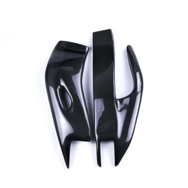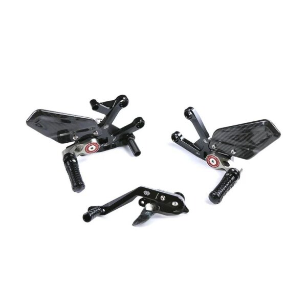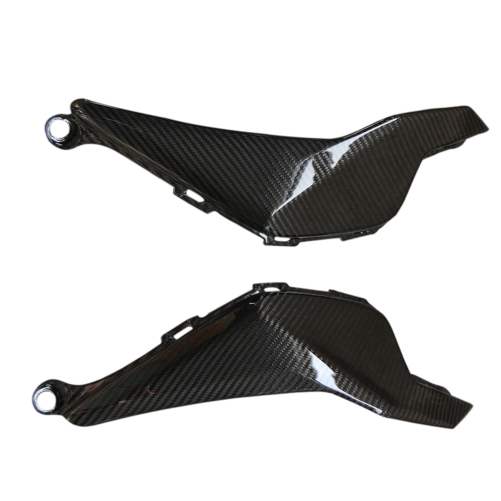
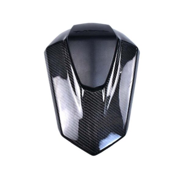
Written by the Chinacarbonfibers Engineering Team. Reviewed by our production engineering team — you can read more about our factory’s manufacturing history on our company page.
Who This Guide Is For
This guide is written for product designers, engineers, brand owners, and purchasing teams who are evaluating carbon fiber for a new part — not for readers looking for wallpaper or texture images. If you’re trying to decide whether a part should be carbon fiber, which fiber grade to specify, or what a factory needs from you before quoting, this page is for you.
Carbon fiber is not a single material — it’s a family of reinforcement fibers, resin systems, weave patterns, and manufacturing processes. The final part’s strength, weight, and cost depend on all of these choices working together, not on the fiber alone. This guide walks through that background in the order a design team actually needs it: what the material is, which grade fits which application, what process to use, and what to prepare before requesting a quote.
1. What Is Carbon Fiber, Really?
Carbon fiber refers to thin filaments (typically 5–10 micrometers in diameter, roughly one-tenth the width of a human hair) composed of more than 90% carbon atoms, arranged in a crystalline structure that gives the fiber very high tensile strength and stiffness relative to its weight.
On its own, dry carbon fiber is not structural. It’s a reinforcement — thousands of filaments bundled into a “tow” (rated by filament count, e.g. 3K = 3,000 filaments, 12K = 12,000 filaments) and woven or laid unidirectionally into fabric. To become a usable part, the fiber must be combined with a resin matrix (usually epoxy) and cured under heat and/or pressure. This combination is technically called carbon fiber reinforced polymer (CFRP) — what most people mean when they say “a carbon fiber part.”
This distinction matters for buyers: a “carbon fiber part” is really the sum of four decisions — fiber grade, weave/orientation, resin system, and curing process. Two parts can use identical fiber and still perform completely differently depending on the other three.
2. Brief Background: From Aerospace Material to OEM Manufacturing
Modern high-performance carbon fiber traces back to Roger Bacon’s work in the late 1950s and the PAN (polyacrylonitrile) precursor process developed in Japan in the early 1960s — still the basis for roughly 90% of carbon fiber produced worldwide today.
For decades, high cost limited carbon fiber to aerospace and motorsport. As precursor and production costs have fallen, it has moved steadily into automotive, motorcycle, drone, sporting goods, and industrial OEM applications — which is where most readers of this guide are evaluating it today. The practical takeaway: carbon fiber manufacturing is a mature, well-documented engineering discipline, not a proprietary secret. Quality differences between suppliers come down to precursor consistency, process control, and inspection discipline — not a hidden formula.
3. Carbon Fiber vs. CFRP: What Buyers Often Misunderstand
A common misunderstanding among first-time buyers is treating “carbon fiber” as a single spec, like ordering “steel.” In practice:
- The fabric is only the reinforcement. Final part performance depends just as much on the resin system, fiber orientation relative to load, layer count, and curing method.
- Cosmetic carbon and structural carbon are different products. A visible-weave hood or trim panel optimized for appearance may use a different layup than a load-bearing bracket optimized for stiffness — even if both use “carbon fiber.”
- “Dry carbon” is not automatically better than “wet carbon.” Dry carbon (prepreg autoclave production) generally gives a lower resin content, lighter weight, and more consistent fiber alignment — but it costs more in tooling and cycle time. For many cosmetic or lower-load parts, wet layup or vacuum infusion is the more rational choice.
If a supplier only ever recommends the most expensive process regardless of the part’s function, that’s usually a sign they’re not evaluating your actual requirements.
4. Common Carbon Fiber Materials Used in OEM Parts
Fiber grade is chosen based on the mechanical demand of the part, not on price alone.
| Grade | Typical Tensile Strength | Typical Tensile Modulus | Common Use |
|---|---|---|---|
| T300 (standard modulus) | ~3,500 MPa | ~230 GPa | Cosmetic exterior panels, interior trim, non-structural body parts |
| T700 (intermediate modulus) | ~4,900 MPa | ~230 GPa | Structural body parts, hoods, roof panels, performance aero components |
| T800 (high modulus) | ~5,500 MPa | ~290 GPa | Motorsport structural parts, lightweight chassis components |
| High-modulus fiber (M40J and similar) | Lower tensile, very high stiffness | 370+ GPa | Stiffness-critical applications where deflection matters more than raw strength |
The figures above are approximate reference ranges for general comparison only, not a guarantee for any specific project. Reference values should be checked against current supplier datasheets — such as Toray, Hexcel, or SGL Carbon — or the actual material batch certificate used for production. Final material selection is confirmed with customers during the quoting stage based on the resin system, laminate design, and project’s load and environmental requirements.
Weave and form options:
- Plain weave — simple over-under pattern, stable, easy to handle, common for cosmetic parts
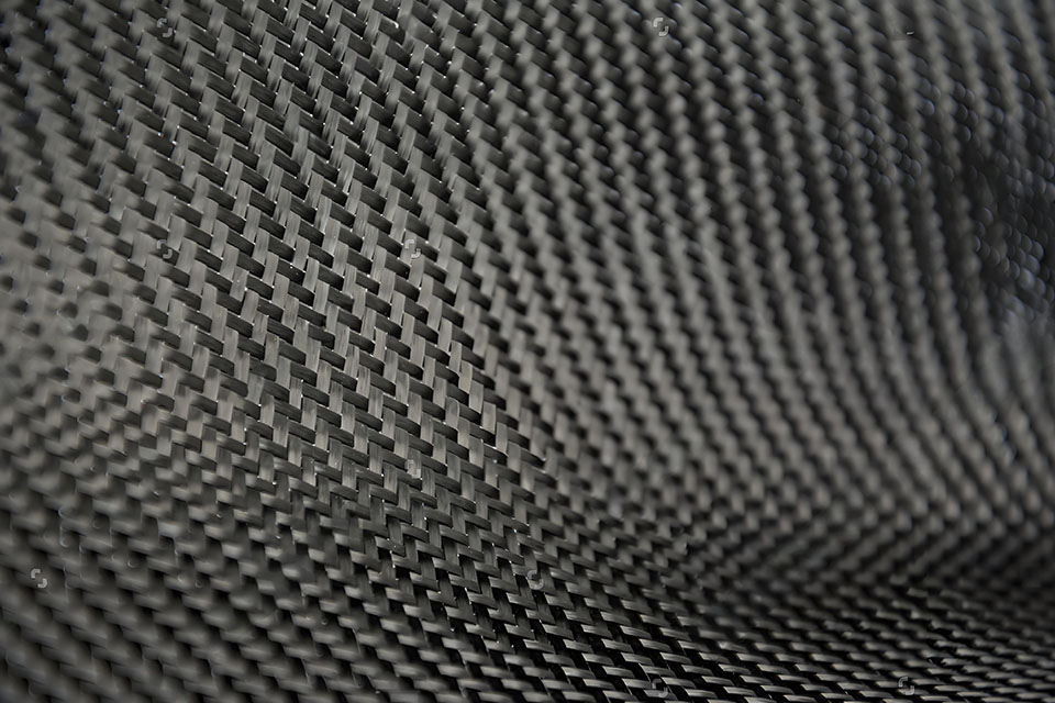
- Twill weave (2×2, 3K/12K) — diagonal pattern, better drape over curved surfaces, the most recognizable “carbon fiber look”
- Unidirectional (UD) — all fibers run one direction; used where load is predictable and directional, delivers the highest strength-to-weight ratio in that direction
- Forged carbon — chopped carbon fiber pieces compression-molded with resin, giving a marbled appearance; faster and cheaper than woven layup, with slightly lower and less predictable mechanical properties
- Carbon fiber mat — randomly oriented short fibers, non-woven, used where quasi-isotropic (equal-in-all-directions) properties are needed

5. Carbon Fiber Manufacturing Processes
| Process | How It Works | Typical Use Case |
|---|---|---|
| Wet layup | Resin applied by hand to dry fabric in an open mold, cured at room temperature | Prototypes, low-volume cosmetic parts, budget projects |
| Vacuum bagging | Wet layup sealed under vacuum to remove air and excess resin before cure | Mid-tier aftermarket parts needing better consistency than wet layup |
| Prepreg autoclave | Pre-impregnated fabric cured under heat and pressure in an autoclave | Aerospace, motorsport, and premium OEM parts requiring maximum strength-to-weight and consistency |
| Compression molding | Chopped fiber or SMC pressed into a heated mold under high pressure | Forged carbon parts, higher-volume production |
| Resin transfer molding (RTM) / infusion | Dry fabric placed in a closed mold, resin injected or infused under vacuum | Structural parts requiring good surface finish on both sides, moderate-to-high volume |
| Filament winding / roll-wrapping | Continuous fiber wound or rolled around a mandrel | Tubes, shafts, hollow structural parts |
| Bladder molding | Inflatable bladder used inside a mold to apply internal pressure during cure | Hollow or complex-section parts like handlebars, frames |
6. Factory Process Selection Table
This is the practical decision matrix our engineering team actually uses when reviewing a new inquiry — sharing it here so buyers can sanity-check their own assumptions before requesting a quote.
| Product Type | Recommended Process | Typical Tooling Option | Best For | Not Recommended For |
|---|---|---|---|---|
| Automotive exterior panel (hood, splitter, diffuser) | Wet carbon or prepreg autoclave | FRP, epoxy, or aluminum mold | Visible carbon finish, medium-size panels, aftermarket fitment | High-load structural parts without engineering/load data |
| Drone / UAV frame | Prepreg plate + CNC machining | Flat plate mold + CNC fixture | Stiffness-to-weight, vibration damping, repeatable geometry | Complex curved shells without a finished CAD model |
| Tube, handle, or shaft | Roll-wrapping or bladder molding | Steel or aluminum mandrel | Continuous fiber strength, torsional stiffness | Irregular internal shapes or variable wall sections |
| Industrial cover / enclosure | Vacuum bagging or RTM | Composite or aluminum tooling | Cost per unit at moderate volume, repeatability | One-off prototypes where tooling cost outweighs the benefit |
| Orthotic or medical support plate | Hot press / compression molding | Matched-metal or heated platen tooling | Controlled flex characteristics, thin consistent sections | Parts needing deep undercuts or hollow cavities |
| Motorcycle fairing / bodywork | Wet carbon or prepreg, depending on budget | FRP or composite mold | Weight reduction on curved-surface bodywork | Ultra-low-budget projects better served by fiberglass-look parts |
| Structural bracket | Prepreg autoclave | Machined aluminum mold | Load path-critical, fatigue-sensitive parts | Parts with no defined load case or safety factor |
7. Design Factors to Prepare Before Starting a Carbon Fiber Project
Carbon fiber is anisotropic — its strength depends on fiber direction, unlike isotropic materials such as aluminum or steel. This changes how a part should be designed from the start:
- 3D file or physical sample — STEP/STP files are preferred; original samples or accurate photos work for reverse engineering
- Wall thickness — copying a metal part’s wall thickness directly is one of the most common and costly design mistakes (see Section 11)
- Fiber direction relative to load — load-bearing ribs, mounting bosses, and high-stress zones need fiber oriented along the load path, not just laid in whatever direction looks good
- Mounting points and inserts — metal threaded inserts, bonded studs, or co-cured hardware need to be specified early, since retrofitting them after molding is difficult
- Surface finish requirement — cosmetic (visible weave) vs. painted/primed vs. functional (no finish requirement)
- Tolerance requirements — composite parts typically hold tighter tolerance in-plane than through-thickness; flag any critical fit dimensions
- Quantity and tooling budget — low-volume projects (prototype to ~50 units) often favor lower-cost tooling (silicone or wet-layup molds); higher volumes justify aluminum or steel tooling with faster cycle times
8. Carbon Fiber Surface Finishes
- High-gloss clear coat — the most common finish for visible-weave exterior parts
- Matte or satin clear coat — increasingly popular for a “stealth” or motorsport look
- Raw sanded finish — unfinished surface for parts that will be painted or hidden
- Primer-ready surface — prepared specifically for post-paint application, matching a body color
- Twill weave vs. forged carbon appearance — twill gives the classic diagonal pattern; forged carbon gives a marbled, non-repeating pattern that some brands specifically request for differentiation
9. When Carbon Fiber Is Not the Right Choice
Carbon fiber is not always the best material for a project, and a supplier that never says so is not giving a full picture. Based on the inquiries we review, carbon fiber is usually not the right choice when:
- the part needs high impact resistance more than low weight — carbon fiber is stiff but can fail abruptly on hard impact, where a more ductile material may perform more predictably;
- the target quantity is too low to reasonably justify tooling cost, and a machined or 3D-printed prototype would answer the same design question faster and cheaper;
- the geometry has deep undercuts or complex hidden mounting structures that are difficult to mold as a single composite part;
- the customer only needs a carbon-look appearance rather than actual CFRP performance — a carbon-effect vinyl wrap or hydro-dip finish may meet the visual goal at a fraction of the cost;
- the available budget is lower than the tooling and layup labor required, and the project would be better served by fiberglass, a carbon/glass hybrid laminate, or CNC aluminum;
- the design is still changing significantly — committing to mold-making before the design is stable usually costs more in rework than it saves in schedule.
In these situations, we typically recommend fiberglass, a carbon/glass hybrid laminate, CNC-machined aluminum, or a lower-cost wet-layup prototype before committing to production tooling — options we regularly discuss as part of scoping a custom carbon fiber project. Being upfront about when carbon fiber isn’t the answer is part of giving accurate engineering advice, not just selling material.
10. Factory Examples: How Process Choice Changes by Product
Client names are withheld for confidentiality, but these reflect the kind of process trade-offs our team walks through on real inquiries:
Automotive hood. For a visible carbon hood, the main concerns are surface weave alignment, clear coat quality, edge trimming, and fitment to the original mounting points. If the part is mainly cosmetic, wet carbon is often enough. If the customer needs lower weight and more batch-to-batch consistency, prepreg autoclave is usually the better recommendation.
Drone/UAV frame plate. For a drone frame build, stiffness-to-weight ratio and vibration control matter more than a glossy appearance. We typically review arm length, motor mounting points, load direction, and target thickness before recommending a T700 or T800 prepreg plate machined by CNC.
Carbon fiber tube. For tube and shaft projects, fiber orientation (unidirectional core, woven outer layer) matters more than the visible 3K weave pattern. Wall thickness consistency, straightness, mandrel design, and insert bonding all need to be confirmed before tooling is committed.
Orthotic support plate. For thin support plates, controlled flex behavior and edge finishing matter more than a visible weave pattern. Hot press or compression molding usually gives more repeatable thickness across a production run than open wet layup.
11. Common Mistakes in Carbon Fiber Product Development
These are patterns we see repeatedly in customer inquiries, and each one adds cost, delay, or part failure if not addressed early:
- Copying a metal part’s wall thickness onto a carbon fiber design. Carbon fiber’s stiffness comes from fiber orientation and layer count, not raw thickness — a direct copy is usually either overbuilt (heavy, expensive) or underbuilt (weak in the wrong direction).
- Choosing dry carbon purely for appearance, on a part with no meaningful weight or stiffness requirement, when a lower-cost wet-layup or forged carbon part would look identical and cost significantly less.
- Underestimating tooling cost and lead time for a one-off or very low-volume part, then being surprised that mold cost dominates the unit price.
- Not confirming mounting points and inserts before mold design, resulting in rework once the part is molded.
- Requesting “the strongest possible part” without providing load, deflection, or environmental data (impact, vibration, UV, temperature exposure) — strength targets need context to be engineered against.
- Assuming small-batch projects need production-grade metal tooling, driving up upfront cost unnecessarily.
12. Before Requesting a Quote: Buyer Checklist
To get an accurate quote and avoid revision cycles, prepare the following before contacting a factory. You can review our full range of carbon fiber capabilities as a starting reference:
- [ ] 3D CAD file (STEP/STP preferred) or original sample / 3D scan
- [ ] 2D drawing with critical tolerances, if applicable
- [ ] Required quantity (prototype, pilot run, or production volume)
- [ ] Surface finish requirement: glossy, matte, raw, or primer-ready
- [ ] Structural vs. cosmetic classification
- [ ] Mounting points, inserts, or hardware requirements
- [ ] Target weight or stiffness benchmark, if known
- [ ] Application environment: UV exposure, moisture, heat, impact, vibration
- [ ] Target unit cost or budget range, and target lead time
13. FAQ
Is carbon fiber always stronger than steel?
By weight, yes — carbon fiber composites typically offer several times the specific strength of steel depending on fiber grade. By absolute strength alone, it depends on the fiber grade, layup, and load direction; carbon fiber is also brittle rather than ductile, so it fails differently than metal under overload.
Is dry carbon better than wet carbon?
Dry carbon (prepreg autoclave) generally produces a lighter, more consistent part with better fiber-to-resin ratio control. Wet carbon (hand layup or vacuum infusion) is more cost-effective and perfectly adequate for many cosmetic or lower-load applications. “Better” depends on the part’s actual requirements, not on price alone.
What’s the difference between 3K and 12K weave?
The number refers to filament count per tow. 3K produces a finer, tighter weave pattern often preferred for smaller or highly visible cosmetic parts. 12K is coarser, faster to lay up, and more commonly used on larger structural or industrial parts where a fine weave pattern isn’t a priority.
Can carbon fiber replace aluminum or steel parts?
Often yes for weight-critical applications, but not automatically. Carbon fiber wins when weight reduction and stiffness-to-weight matter more than raw impact toughness or low unit cost. For parts requiring high impact resistance, ductility, or very low piece cost at scale, aluminum or steel may still be the better engineering choice.
How much does a custom carbon fiber mold cost?
It depends heavily on part size, geometry complexity, and tooling material (silicone, composite, or machined aluminum/steel). As a rough guide, tooling is usually one of the largest fixed costs in a new custom carbon fiber project — share your part geometry and target volume for an accurate quote.
What is the MOQ for custom carbon fiber parts?
MOQ varies by part complexity and whether tooling already exists. Standard parts with existing tooling can sometimes be ordered in small quantities; fully custom parts requiring new tooling typically have a higher MOQ to justify the mold investment.
Do I need a 3D CAD file for a custom carbon fiber part?
It’s strongly preferred, since it lets us confirm wall thickness, mounting features, and tolerances before mold design. If you don’t have a CAD file, we can often work from an original sample, 3D scan, or detailed photos with measurements.
Which is better for automotive parts: wet carbon or dry carbon?
For cosmetic exterior panels without significant structural load, wet carbon is often sufficient and more cost-effective. For performance or structural automotive parts (splitters under aerodynamic load, structural hoods), dry carbon prepreg generally gives more consistent, lighter results.
Why do small carbon fiber orders have a high unit cost?
Tooling and setup costs are largely fixed regardless of order size, so they’re spread across fewer units on a small order. Hand layup labor time per part also doesn’t scale down proportionally with quantity.
Can carbon fiber parts include threaded inserts?
Yes — metal threaded inserts can be bonded in post-cure or co-cured into the layup during molding, depending on the part’s load requirements. This should be specified at the design stage so mounting bosses can be engineered correctly.