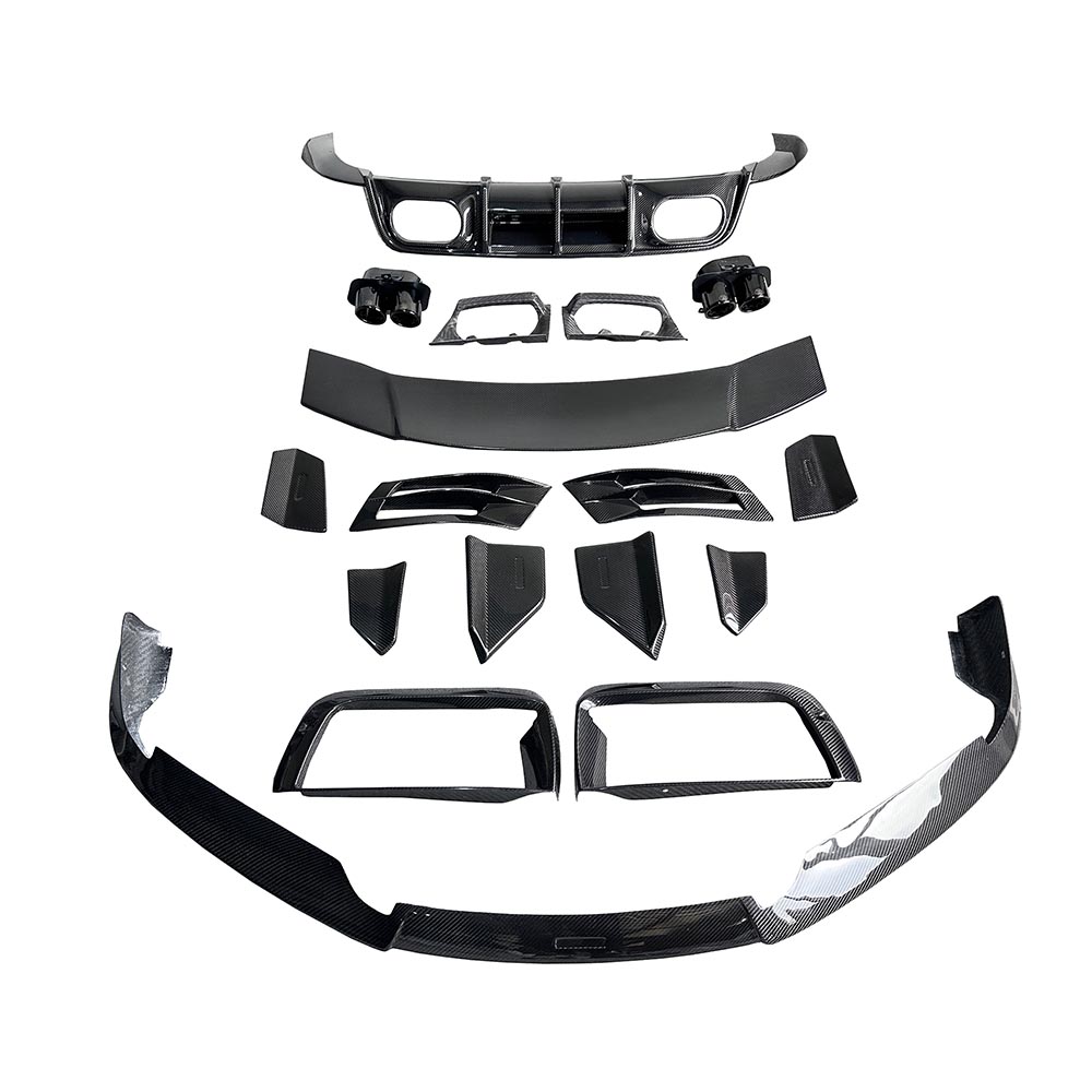
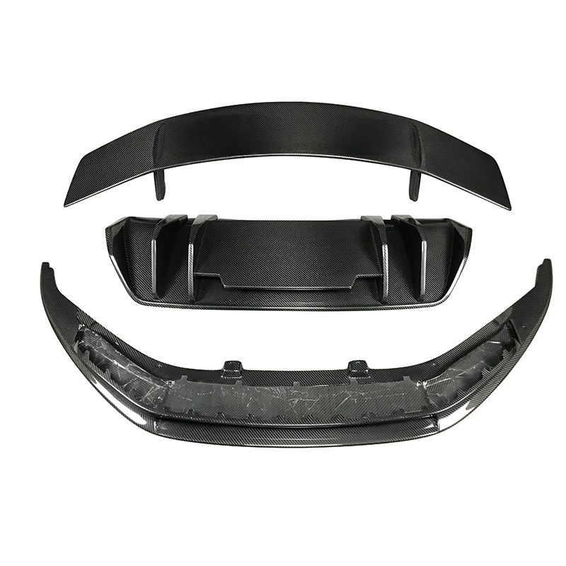
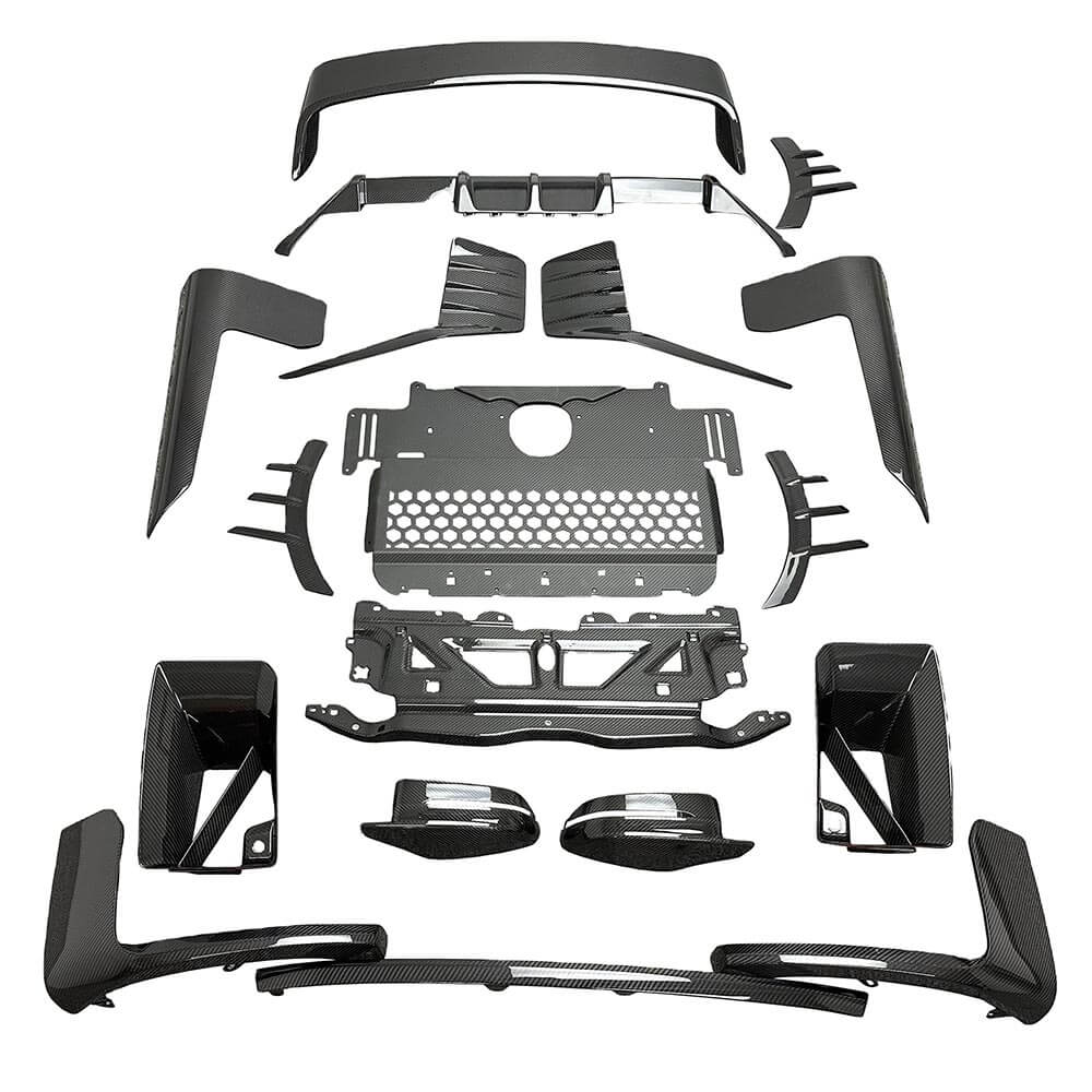
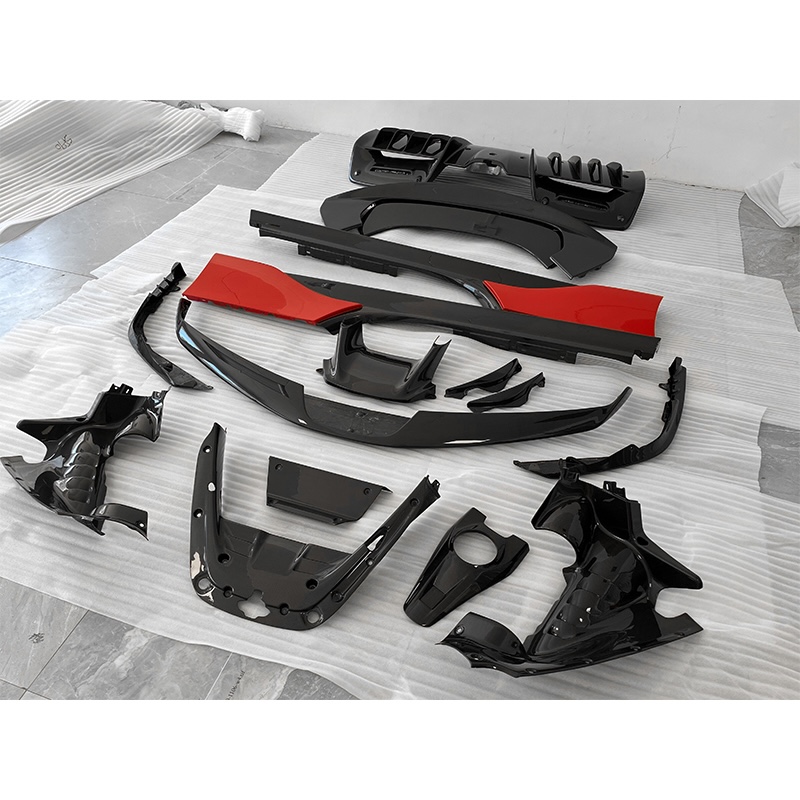

Reviewed by the SC Composite Engineering Team. Our team works with visible carbon fiber surfaces using prepreg autoclave, vacuum bagging, compression molding, CNC trimming, and clear-coat finishing for automotive, industrial, and sporting applications.
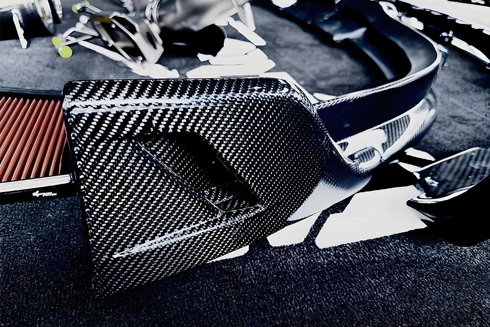
Carbon fiber usually appears black or dark gray, with visible fibers arranged in woven, parallel, or random patterns. Its final appearance depends on the fiber form, weave style, tow size, surface resin, clear coat, mold finish, part geometry, and viewing angle.
Not all carbon fiber shows the classic checkerboard pattern people picture. Some weaves are diagonal, some are square grids, and some show only parallel lines with no crossing pattern at all. Forged carbon looks completely different again — random, marble-like, with no repeating structure. Gloss usually comes from a clear coat or resin surface rather than the fiber itself, and it isn’t a reliable way to tell how a part was manufactured.
This guide focuses specifically on how carbon fiber looks — not on how to tell real from fake, not on color customization, and not on comparing dry and wet manufacturing processes. If you’re trying to identify a genuine part, choose a color, or compare production methods, those topics are covered in more detail elsewhere on our site.
| Carbon fiber form | Typical appearance | Common visual impression |
|---|---|---|
| 2×2 Twill | Diagonal repeating pattern | Dynamic, premium, automotive |
| Plain weave | Small square checkerboard | Neat, technical, symmetrical |
| Unidirectional (UD) | Parallel straight lines | Minimal, structural, directional |
| Spread tow | Wide, flat checker pattern | Modern, clean, large-scale |
| Satin weave | Longer floating pattern | Smooth, flowing, refined |
| Forged carbon | Random chips or marble-like pattern | Organic, irregular, distinctive |
This table describes appearance only, not performance ranking. The same weave style can look proportionally different depending on tow size, areal weight (GSM), part curvature, and clear-coat thickness. “Forged carbon” is not a weave at all — it’s the appearance created by randomly oriented chopped fibers or fiber chips, which is why it never repeats the same way twice.
In addition to twill, plain weave, and UD, buyers may also encounter spread-tow, satin-weave, and forged-carbon surfaces in automotive, sporting, industrial, and consumer applications.
A single carbon fiber filament is extremely thin — far thinner than a human hair. On its own, one filament doesn’t look like anything you’d recognize as “carbon fiber.” Thousands of these filaments are bundled together into a tow, and it’s the arrangement of tows — not the individual filaments — that creates the checkerboard or diagonal pattern people associate with the material.
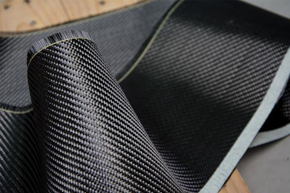
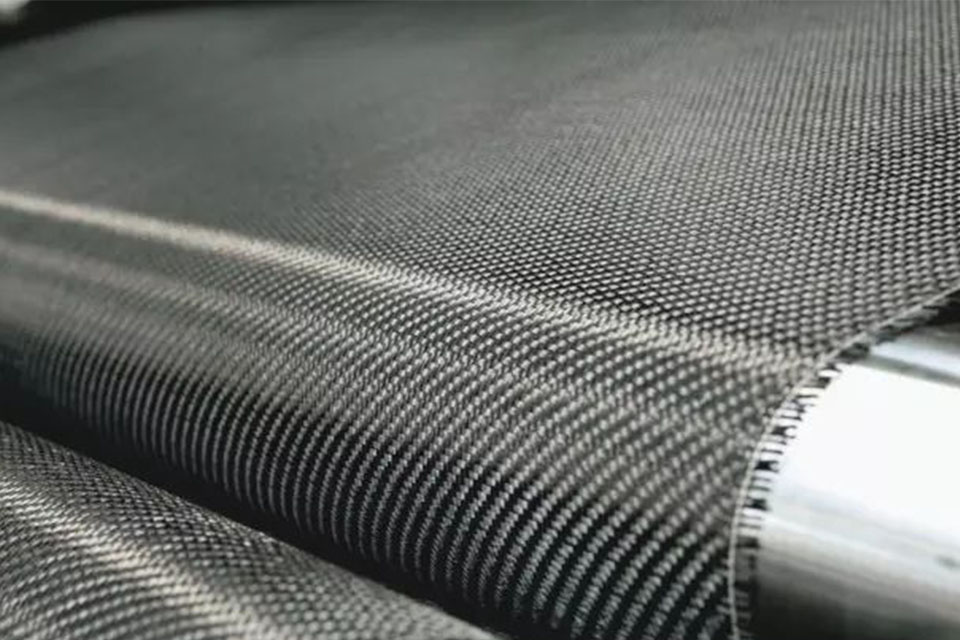
Before it’s combined with resin, carbon fiber fabric looks noticeably different from a finished part:
Carbon fiber prepreg — fabric pre-impregnated with a controlled amount of resin — looks tighter and more uniform than dry fabric. The surface may feel slightly tacky and is sometimes covered with a protective backing film. Because it hasn’t been cured yet, prepreg doesn’t have the hardness or final gloss of a finished part; the weave pattern is visible but appears “flatter” than it will after curing.
Once cured, carbon fiber reinforced polymer (CFRP) becomes a rigid composite. The fiber pattern is typically visible through a layer of clear or tinted resin, and the surface finish — from the mold, from sanding, or from a topcoat — determines whether the final look is glossy, matte, semi-matte, or a raw machined appearance.
Twill weave shows a continuous diagonal pattern, with the visual “grain” running at roughly a 45-degree angle. This gives it a sense of motion that plain weave doesn’t have. Compared with a similar plain-weave fabric of the same tow size and areal weight, twill usually offers better drapability over curved surfaces, which is one reason it’s so common on automotive interior and exterior trim. On parts that come in symmetrical pairs, opposite sides usually need to be laid up as mirror images of each other to keep the diagonal direction visually consistent — this doesn’t happen automatically.
In plain weave, tows alternate over and under each other in a simple, regular pattern, producing a tight, square checkerboard look. It reads as more compact and technical than twill, and on small parts it often looks especially precise. On complex, deep curves, plain weave can be more prone to local tightening or gapping in the pattern compared to twill.
Unidirectional (UD) fiber runs in parallel straight lines with no crossing pattern at all. People unfamiliar with composites sometimes don’t recognize UD as carbon fiber because it lacks the checkerboard look entirely. UD can be used as a hidden structural layer or as a visible surface layer, and because all the fibers run in one direction, the reflected light shifts noticeably as the viewing angle changes along that axis.
Spread-tow fabric flattens and widens each tow bundle, producing a larger, flatter grid with fewer crossing points than standard weaves. This gives a more modern, smooth look compared to traditional 3K patterns. On large surfaces the effect is striking; on small parts, the pattern can look disproportionately large relative to the part size.
Satin weave has longer floating tows, which creates a more continuous, flowing surface pattern with a softer look than plain weave. It’s often chosen for parts needing good curve conformity and a refined appearance — though “refined” doesn’t automatically mean it outperforms twill; the right choice depends on the project.
Forged-carbon-style surfaces are generally produced from discontinuous carbon fibers, chopped tows, prepreg chips, or molding compounds arranged without a repeating woven pattern. Visually, it resembles black marble, cracked ice, or irregular cloud patterns — there’s no diagonal alignment and no two parts look exactly the same. This makes it a popular choice for buyers who want each part to look genuinely unique.
| Tow size | General visual scale | Typical visual character |
|---|---|---|
| 1K | Very fine | Delicate and detailed |
| 3K | Medium-fine | Familiar and balanced |
| 6K | Larger | More pronounced pattern |
| 12K | Broad | Bold and industrial |
Tow size alone doesn’t determine the exact size of the visible squares in a finished part. Fabric construction, weave style, areal weight, and tow spacing all affect the final pattern as well. Two suppliers both quoting “3K twill” can still produce noticeably different-looking squares, and even the same tow size at 200 GSM versus 240 GSM can look visually denser or sparser. Because of this, it’s not enough to specify tow size alone in a purchase order. Buyers should also review the weave, GSM, pattern scale, and other carbon fiber fabric specifications, along with a physical sample or an approved reference photo.
Carbon fiber’s surface isn’t a flat, uniform black plane. Fiber tows running in different directions reflect light differently — one set of tows may look brighter while the crossing set looks darker, and reversing the viewing angle swaps which areas look light and which look dark. This is what produces the “light and dark checkerboard” effect visible in photos. This effect is purely optical and isn’t, on its own, a reliable way to distinguish real carbon fiber from fake.
A clear resin or clear-coat layer adds visual depth to the fiber pattern underneath. A thicker clear coat can make the weave look deeper and more three-dimensional, while a thinner or matte coating reduces highlights. Coating thickness on its own says nothing about the structural quality of the part.
Showroom lighting tends to produce concentrated, sharp highlights. Overcast daylight evens out the pattern. Camera flash can exaggerate any surface waviness, and phone camera HDR processing often makes the weave look more dramatic than it is in person. When comparing appearance across samples or batches, it helps to use consistent lighting and viewing angle rather than relying on photos taken under different conditions.
High reflectivity, strong pattern depth, and a mirror-like surface. Gloss also shows fingerprints, small scratches, waviness, and dust more readily than other finishes. It is widely used on visible automotive exterior parts because it emphasizes weave depth and contrast.
Softer reflection and lower pattern contrast, giving a more technical, understated look. A matte surface does not by itself indicate whether a part is dry or wet carbon. Surface finish and manufacturing method are separate considerations.
Sits between gloss and matte — some pattern depth remains, but highlights are softer. Commonly used for automotive interiors and consumer products where a subtler shine is preferred.
“Raw carbon” isn’t one single standard look. It can mean a mold-side surface straight off the tool, a trimmed-and-sanded surface, or an uncoated machined surface — and each looks different. Buyers should specify clearly whether a clear coat is expected, since a raw finish can carry light resin texture, sanding marks, or a mold-transfer pattern.
Flat fabric has to shear and reposition itself when it’s draped over a three-dimensional curve. Square patterns can shift toward a diamond shape, and twill angles can rotate slightly from their original direction. The tighter the curve, the more the pattern shifts from its flat-sheet appearance.
Deep recesses, small radii, and sharp vertical edges make draping more difficult. These areas sometimes require splitting the fabric, adding notches, or overlapping small sections. Prioritizing perfectly continuous pattern lines in these areas can come at the expense of layup stability, so structural requirements generally take priority over decorative continuity.
Cutting fabric the same way for both a left and right part results in tow directions that mirror incorrectly rather than matching visually. Getting a symmetrical pair — like matching mirror caps or side skirts — requires planning the cutting and layup direction specifically for symmetry; it isn’t something that happens by default and can’t be fixed after painting.
Some amount of pattern shift is a normal result of fabric conforming to a curved shape. Sudden, uneven twisting, wrinkling, folding, or a clearly off-angle section is different from gradual, expected distortion, and should be evaluated against an approved sample rather than assumed to be acceptable or unacceptable on sight.
Not every complex part can be made from a single continuous piece of surface material. Openings, deep pockets, tight recesses, and complicated curves sometimes require the fabric to be split into sections. Seam locations are usually planned during design rather than discovered afterward, and a seam by itself does not necessarily compromise structural integrity.
A butt joint gives a flatter, cleaner look but requires tighter process control to execute well. An overlap can show a visible change in color or thickness at the joint. Whether visible overlaps are acceptable for a given part should be defined explicitly in the appearance standard, not assumed.
Left and right parts can be laid up as mirror images of each other, and a center line can be designed with a V-shaped or symmetrical pattern. This takes extra cutting precision, positioning, and labor — it is not automatically included in a standard quote and needs to be confirmed before tooling begins.
Hoods, side panels, and interior trim pieces are separate parts, so their weave patterns don’t naturally line up once assembled. Achieving visual continuity across an assembly requires a shared reference point, consistent orientation across parts, and careful attention to fit tolerances and gaps.
| Visual feature | What it looks like | Usually acceptable? | What to specify |
|---|---|---|---|
| Minor weave shift | Gradual change in pattern angle | Often | Approved limit/photo |
| Print-through | Faint underlying texture | Depends on finish class | Lighting and viewing distance |
| Pinholes | Tiny surface dots | Usually not for Class A | Maximum size/count |
| Resin-rich area | Darker or glassier patch | Depends | Size and location limit |
| Dry spot | Pale or poorly wetted fibers | Normally not acceptable | Reject criteria |
| Wrinkle | Folded or distorted fibers | Often unacceptable | Structural/cosmetic evaluation |
| Seam line | Controlled joining line | May be acceptable | Approved position |
| Clear-coat wave | Wavy reflected light | Depends | Gloss standard |
| Edge exposure | Visible laminate layers | Depends on edge finish | Sealed/painted/raw |
Acceptance depends on the agreed cosmetic class, part location, manufacturing process, and approved sample. The table above is a practical guide, not a universal rejection standard.
A gradual pattern shift from draping is different from a sudden, sharp distortion — the latter is more likely to indicate a process issue.
These appear as tiny surface dots and are generally not acceptable on Class A visible surfaces, though tolerance varies by part class and application.
These show up as noticeably darker/glossier patches (resin-rich) or paler, poorly wetted fiber (resin-lean). Both are best judged against a physical reference sample rather than description alone.
This is when the underlying weave texture becomes visible through the surface coating, most noticeable on glossy finishes under side lighting. A single frontal photo often won’t reveal it clearly.
These are surface coating issues rather than problems with the carbon fiber layer itself, and they’re worth distinguishing clearly during inspection.
Before tooling, we normally review the CAD model to identify visible Class A surfaces — meaning the primary cosmetic surfaces seen by the customer — as well as deep recesses, tight radii, return edges, and likely seam locations. For paired parts, we also confirm whether the customer expects matching or mirrored weave directions. In practice, this planning stage usually covers:
These choices affect material cutting, layup time, rejection risk, and quotation, so they should be agreed before the first sample rather than corrected after clear coating.
That description alone leaves too much undefined. A complete specification for custom carbon fiber parts should also cover weave type, tow size, visible pattern scale, fiber direction, finish level, gloss level, seam allowance, symmetry requirements, edge treatment, and acceptable cosmetic defects.
Screens, exposure settings, lighting, and photo editing all change how carbon fiber appears in images. Before a large production run, it’s worth approving a physical sample and comparing later production against it directly. A golden sample should be labeled with the part number, revision, approved surface, material or fabric reference, finish level, approval date, and customer approval record.
As practical starting points rather than universal standards:
These are starting points to agree on per project — not a fixed industry-wide rule.
2×2 twill is common, typically in gloss or satin, across both carbon fiber car parts and carbon fiber motorcycle parts. UV resistance, left/right symmetry, and pattern direction across adjacent panels are the main things to plan for.
Fine 3K, plain, or twill weaves in satin or matte reduce glare. Seam placement and matching existing OEM trim panels matter here.
Plain, twill, or a painted surface, chosen based on whether the part is a visible A-surface or a hidden structural layer — there’s no need to pay for a premium appearance on a surface no one will see.
Pattern scale should match the size of the part — for long, slender items like shafts, fiber direction is worth paying attention to; for multi-piece sets, batch consistency matters most.
1K, fine 3K, spread tow, or forged carbon are common choices. Pattern centering, logo placement, and edge treatment tend to matter more here than the raw material name alone.
Does all carbon fiber have a checkerboard pattern? No. UD, forged, braided, and painted CFRP surfaces may show no traditional checkerboard at all.
Is glossy carbon fiber always dry carbon? No. Gloss is mainly a function of mold surface, resin layer, sanding, and clear coat — not the manufacturing process by itself.
Is a perfectly straight weave always better? Not necessarily. On complex curved surfaces, some pattern distortion is often unavoidable. What matters more is whether the result is smooth, symmetrical, and repeatable — not whether every square stays perfectly uniform.
Does a larger weave mean lower quality? No. A larger visible pattern can simply come from 12K tow, spread-tow fabric, or a specific fabric design choice.
Does matte carbon fiber have no clear coat? Not necessarily. A matte look can also come from a matte clear coat rather than the absence of one.
Is forged carbon the same as woven carbon? No. Both can be CFRP, but the visible fiber form and pattern structure are fundamentally different.
Carbon fiber itself is naturally black to dark gray, with visible fiber tows arranged according to the weave or fiber form; colored effects normally come from coatings, pigments, or hybrid fibers rather than the raw fiber itself.
Because of the interplay between fiber tow direction and the transparent resin layer over it, which creates visual depth and shifting reflections.
Because tows running in different directions reflect light differently, so which areas look light or dark shifts as your viewing angle changes.
2×2 twill is one of the most widely recognized and commonly specified visible patterns for automotive and consumer carbon fiber parts, though it isn’t the right choice for every application.
Yes — unidirectional fiber, painted CFRP, and some structural or chopped-fiber layers don’t show a traditional weave pattern.
Because a flat, two-dimensional fabric has to shear and reposition itself to conform to a three-dimensional curved surface.
Only if visual symmetry is a stated project requirement — it isn’t automatic and needs to be planned during cutting and layup.
Yes. Fabric batch, supplier, resin, curing, and clear-coat/polishing steps can all introduce minor visual variation, which is why working from an approved sample is worthwhile.
There’s no single “look” for carbon fiber. Its final appearance is shaped by fiber form, weave style, tow size, layup direction, part curvature, resin, and surface finish working together. For OEM buyers, simply specifying “3K carbon fiber” isn’t enough — the more reliable approach is to define weave, direction, gloss level, seam locations, defect standards, and an approved physical sample up front.
Send us your STP file, physical reference part, or approved appearance sample. Before tooling, we can evaluate visible weave direction, likely seam locations, mirrored layup requirements, surface finish, and suitable manufacturing processes for your quantity and cosmetic standard.