Carbon fiber parts are made by combining carbon fiber reinforcement with a polymer resin, shaping the material in a mold, consolidating it under vacuum or pressure, and curing it at a controlled temperature. The exact sequence of steps depends on the part’s geometry, structural requirements, cosmetic finish, tolerances, and production volume — a decorative interior trim panel and a load-bearing structural tube are rarely made the same way, even though both are “carbon fiber parts.”
In a typical custom carbon fiber parts project, the process runs through CAD review, tooling design and manufacture, material cutting, ply layup, vacuum bagging, curing, demolding, CNC trimming, surface finishing, and final inspection. Below, we walk through each of these stages the way we actually run them on our own production floor, including the decisions, trade-offs, and failure points that most general overviews skip.
Process at a glance:
Project Requirements → CAD Review → Process & Tooling Selection → Mold Manufacture → Material Cutting → Ply Layup → Vacuum Bagging → Curing → Demolding & Trimming → Finishing → Inspection
Reviewed by: Composite Engineering Team, Chinacarbonfibers Co., Ltd. Based on: our manufacturing experience with custom automotive, motorcycle, industrial, sports, and structural carbon fiber components — see our production facilities for a closer look at where these parts are made Our manufacturing and closely coordinated tooling capabilities include: prepreg autoclave molding, vacuum infusion, compression molding, bladder molding, CNC trimming and drilling, and clear-coat surface finishing Last updated: July 2026
Carbon Fiber Is a Composite, Not a Single Material
A roll of carbon fiber cloth is not, by itself, a structural material. Carbon fiber consists of bundles of extremely thin filaments, each much thinner than a human hair; individual filaments are strongest in tension along their length. It becomes a usable part only after it is combined with a resin matrix, laid up in a defined orientation, and cured into a solid laminate — a process that allows the final composite to also handle bending, compression, and shear, depending on how the plies and matrix are engineered.
| Component | Function |
|---|---|
| Carbon fiber reinforcement | Carries most of the tensile and bending load |
| Resin matrix (typically epoxy) | Binds the fibers together, transfers load between them, and protects the laminate from moisture and impact |
| Core material (foam, honeycomb) | Adds stiffness and thickness without adding significant weight, used in panels and shells |
| Metal or composite inserts | Provides durable threaded or load-bearing mounting points |
| Clear coat / paint system | Protects the cosmetic surface and provides UV resistance |
The fiber and resin together — not either material alone — determine the part’s final strength, stiffness, weight, and appearance. This is why two parts using the exact same carbon fiber cloth can have very different mechanical performance depending on resin selection, fiber orientation, and cure quality.
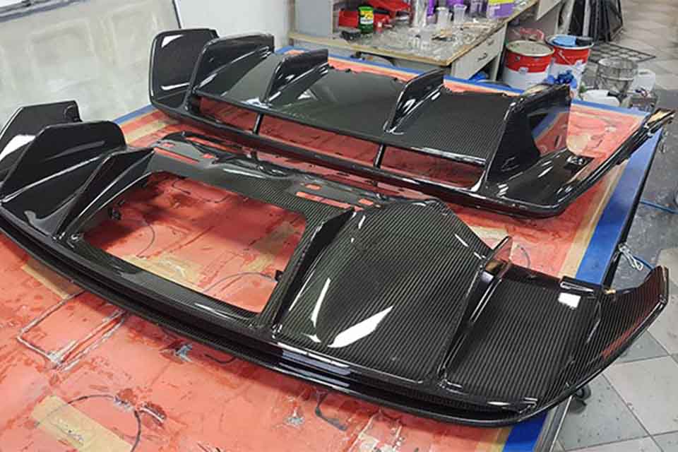
The 10-Step Carbon Fiber Parts Manufacturing Process
Step 1: Define the Part Requirements
Before any material is cut, we confirm what the part actually needs to do. This step is frequently skipped in general overviews, but it is where most of the manufacturing decisions downstream actually get made.
Key questions we work through with a customer:
- Is the part structural (load-bearing) or cosmetic (non-structural)?
- What loads, vibration, or impact will it see in service?
- What temperature range and chemical/UV exposure will it face?
- What is the target weight and thickness?
- What surface finish is required (gloss, matte, painted)?
- Where are the mounting points and how much load do they carry?
- What is the initial order quantity, and what is the expected annual volume?
- What dimensional tolerances and documentation are required?
A cosmetic cover panel may only need a decorative outer ply with light backing reinforcement. A load-bearing bracket or tube needs controlled fiber orientation, a laminate thickness selected according to the expected loads and geometry, reinforced insert zones, and, where required, third-party testing or customer engineering approval before production starts. Treating both the same way is one of the most common causes of either overpriced cosmetic parts or underbuilt structural ones.
Step 2: Review or Create the 3D Model
Custom carbon fiber projects typically start from one of three inputs:
- A customer-supplied STEP file
- An original sample part that needs to be 3D scanned and reverse-engineered
- Reference photos or a surface-only model that must be rebuilt from scratch
STEP files are preferred over STL because STEP retains true engineering geometry (surfaces, features, tolerances), while STL is a faceted mesh approximation. Converting STL to STEP does not automatically recover accurate wall thickness, draft angles, or feature intent — it has to be rebuilt.
Even with a “complete” CAD file, we check for:
- Draft angles for demolding
- Fillet/corner radii (sharp internal corners are a common source of defects — see Step 6)
- Undercuts that will trap the part in the mold
- Parting line location
- Mating and assembly surfaces
- Wall thickness consistency
Factory note: In our experience, many quoting delays are not caused by the carbon fiber process itself — they’re caused by incomplete CAD data. A surface model can look complete on screen while omitting wall thickness, bonding flanges, insert positions, trim lines, and mating features that only show up once someone tries to actually build the mold.
Step 3: Select the Manufacturing Process
Selecting the right process has a direct impact on tooling cost, lead time, and achievable part quality — it deserves more than a single sentence, which is why we walk through it in detail below.
| Process | Best suited for | Tooling cost | Typical part quality | Production volume | Typical limitations |
|---|---|---|---|---|---|
| Wet layup | Prototypes, cosmetic one-offs | Low | Moderate, operator-dependent | Very low | Higher resin/fiber variability |
| Vacuum-bagged wet layup | Custom panels, low volumes | Low–medium | Better consolidation than open layup | Low | Resin content still hard to control precisely |
| Vacuum infusion (VARTM) | Large shells, panels | Medium | Good, consistent resin distribution | Low–medium | Requires resin-flow planning to avoid dry spots |
| Prepreg + oven cure | High-quality custom parts | Medium | High | Low–medium | Limited consolidation pressure vs. autoclave |
| Prepreg + autoclave cure | Lightweight structural / premium cosmetic parts | Medium–high | Very high | Low–medium | Higher equipment and processing cost |
| Compression molding (matched metal tooling) | Repeatable molded parts | High | High and highly repeatable | Medium–high | Expensive tooling; economical only at volume |
| Forged/chopped carbon compression molding | Complex geometry, distinctive marbled appearance | Medium–high | Repeatable | Medium–high | Usually requires matched tooling and controlled charge placement; mechanical properties are less directional than continuous-fiber laminates |
| Filament winding | Tubes, shafts, pressure vessels | Specialized | High axial/hoop strength | Medium–high | Limited to winding-compatible geometries |
We normally select a process using what we think of as Our Five-Factor Process Selection Framework: weighing geometry, structural load, cosmetic requirement, tolerance, and annual quantity together, rather than any one factor in isolation. A part that looks simple can still require autoclave processing or another high-consolidation method if the tolerance or load case demands it; a visually complex part can sometimes be built economically with wet layup if it’s a true one-off.
This table provides a high-level comparison of several common composite manufacturing methods. For higher-volume production using closed, matched tooling, see our dedicated guide to the RTM carbon fiber process. And if the goal is the distinctive marbled, chopped-fiber appearance rather than continuous-fiber performance, our guide to how forged carbon fiber is made covers that process in more depth.
Step 4: Design and Manufacture the Mold
Mold material and construction have a direct effect on cost, cycle time, achievable production volume, and dimensional consistency — this stage is worth understanding on its own; see our closer look at how a carbon fiber mold is made for the full tooling workflow.
| Tool type | Typical use | Relative cost | Typical production suitability based on our manufacturing experience |
|---|---|---|---|
| Epoxy/fiberglass composite mold | Prototypes and low-volume production | Low | Roughly 25–60 parts before refinishing |
| Aluminum mold | Repeated prepreg/autoclave production | Medium–high | Roughly 500–1,000 parts |
| Steel matched mold | Compression molding, high-volume production | High | Roughly 5,000 parts or more |
| Silicone bladder / internal mandrel | Hollow tubes and enclosed shapes | Project-specific | Depends heavily on geometry and bladder service life |
Actual mold life depends on part geometry, cure temperature, release conditions, handling, and maintenance.
Why one mold is not always enough: A single mold has a fixed cycle time — the time needed to lay up, cure, and demold one part (or one set of parts, for multi-cavity tools). If a single-cavity prepreg mold typically produces only one finished part per working day, and a customer needs 500 units a year, the math simply doesn’t work without either a multi-cavity tool or multiple molds running in parallel. This relationship between mold count, cycle time, and annual volume is an important driver of quoted lead time and unit price, but it is rarely explained clearly to buyers upfront.
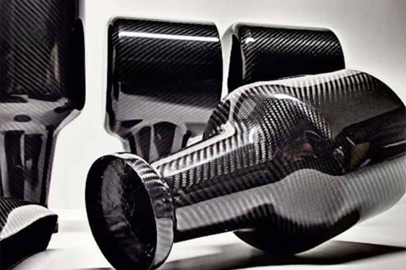
Step 5: Cut and Prepare the Carbon Fiber
Material is cut to ply patterns generated from the CAD model, using digital nesting to minimize waste. For prepreg materials, this includes tracking cold storage time and controlled thawing before use. For projects that require traceability, material batch and storage records can be maintained so parts can be linked to the relevant material lot.
Factory note — weave direction vs. load direction: The visible weave pattern on the finished surface is largely a cosmetic decision. The structural plies underneath it should be oriented to follow the part’s actual load paths — 0°, 90°, and ±45° orientations placed according to where bending, torsion, or tension will occur — not simply mirrored to match the surface weave. A part can look identical from the outside while having very different strength depending on what’s underneath the cosmetic ply.
Step 6: Lay Up the Carbon Fiber Plies
This is where cosmetic surface plies, structural backing plies, local reinforcement patches, core material, and metal inserts are placed in sequence, following the ply schedule from the design.
Why sharp corners cause problems: Carbon fiber cloth does not conform well to sharp internal corners. Forcing it into a true 90° corner tends to cause bridging (the fabric spans the corner instead of following it), which leaves a resin-rich void behind the fiber and a weak spot in the laminate. This is why internal corners are typically designed with a radius, and why some geometries are better split into separate parts that are bonded together, CNC-machined to shape after cure, or built around a removable insert rather than molded as one sharp-cornered piece.
Step 7: Vacuum Bag the Laminate
A vacuum bag system typically consists of, in order: the mold surface, release agent, the carbon laminate itself, peel ply, release film, breather fabric, the vacuum bag film, sealant tape, and a vacuum port.
Before curing, the bag is leak-tested to confirm vacuum integrity. Proper bagging removes trapped air, controls excess resin, and helps prevent the bridging described in Step 6.
Step 8: Cure the Carbon Fiber Part
Curing chemically hardens the resin into its final, permanent state. The specific cycle — temperature, pressure, dwell time, and heating/cooling rate — must follow the resin system and laminate design; it is not a single fixed number across all materials.
As a general reference point, many prepreg systems cure in the region of 120–180°C, and autoclave processing typically applies pressure in a multi-bar range — but the actual cycle used on any given part must follow the material’s technical datasheet and a validated process, not a generic figure copied from an article. This detail matters in practice: running the wrong cycle for a given resin system is one of the more common causes of under-cured or over-cured laminate, which can silently reduce a part’s strength even when it looks fine on the outside.
Step 9: Demold, Trim, and Machine the Part
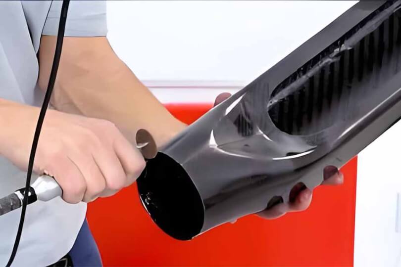
Once cured, the part is removed from the mold and trimmed to final dimensions using CNC routing, dedicated trimming fixtures, or controlled manual trimming, followed by drilling and datum positioning for holes and mounting features.
Factory note: A molded surface can be dimensionally accurate straight out of the mold, but the part isn’t actually finished until trim lines, hole positions, and mating interfaces are correctly located relative to the design datums — not just relative to the mold. This is a step buyers often assume is automatic; it isn’t, and it’s where fitment problems on assembled parts most often originate.
Step 10: Finish and Inspect the Part
Finishing options range from a raw prepreg finish to gloss or matte clear coat, satin finishes, paint-ready primer, and UV-resistant topcoats, plus pinhole filling, sanding, and polishing where a cosmetic-grade surface is required.
Inspection is scoped to the part, not applied as a blanket checklist.
Routine in-house checks may include:
- Visual inspection and weave alignment
- Dimensional inspection against the CAD model
- Thickness and weight verification
- Fitment/assembly trial
Project-specific documentation or third-party services can include:
- Material lot records
- Certificate of Conformance (CoC)
- Tap testing for gross delamination
- Third-party ultrasonic inspection
- Formal cure records and full material traceability
These are scoped and agreed with the customer before quotation, rather than applied by default to every order.
Common Carbon Fiber Manufacturing Defects
Understanding these failure modes helps buyers evaluate both part quality and a supplier’s process control, and helps explain why two visually identical parts can have very different real-world durability.
| Defect | Typical cause | How it’s prevented |
|---|---|---|
| Voids / pinholes | Air leakage in the vacuum bag, bridging, poor consolidation | Leak testing, debulking during layup, correct bagging sequence |
| Resin-rich areas | Poor compaction, ply movement during bagging | Controlled layup pressure and ply stabilization |
| Dry spots | Incomplete resin flow during infusion | Resin-flow planning, trial validation, and correct inlet/vent placement |
| Delamination | Surface contamination, incorrect cure cycle, or impact damage | Surface prep control and a validated, followed cure cycle |
| Warpage | Unbalanced (asymmetric) laminate, or demolding before full cure | Symmetric ply schedules and controlled cool-down before demold |
| Weave distortion | Fabric stretching or shifting around complex curves | Ply templates, relief cuts, and careful hand placement |
| Incorrect fitment | Inaccurate CAD data, trim fixture error, or missing datum references | Datum planning and first-article inspection before production release |
| Cracking around holes | Drilling without local reinforcement | Correct drilling tools and reinforced hole zones in the laminate |
Carbon Fiber Manufacturing: What Customers Often Get Wrong
These are assumptions we run into regularly when reviewing new projects — and correcting them early usually saves both cost and lead time.
“More carbon fiber layers always mean a stronger part.” Not necessarily. Fiber orientation relative to the actual load path usually matters more than raw layer count. Adding plies in the wrong direction adds weight and cost without adding useful strength — and can even make a part stiffer in the wrong axis while remaining weak in the one that matters.
“Autoclave is always the best process.” Autoclave curing gives excellent consolidation and consistency, but it isn’t required for every part. For many cosmetic or moderately loaded components, oven-cured prepreg or vacuum infusion delivers adequate performance at a lower cost — paying for autoclave processing on a part that doesn’t need it is a common way projects get overpriced.
“A complete CAD file means production can start immediately.” A finished-looking 3D model still needs a Design-for-Manufacturability (DFM) review — draft angles, corner radii, wall thickness, parting lines, and insert locations all have to be checked against the chosen process before tooling starts. Skipping this step is a common cause of delays and rework later in the project.
“Carbon fiber parts are expensive because the carbon fiber material is expensive.” Raw material is often a smaller share of the final cost than people expect. Tooling design and machining, skilled layup labor, cure equipment time, CNC trimming, finishing, and inspection typically make up the majority of the cost — which is also why low-volume orders cost more per part than higher-volume production using the same material.
How We Approach Different Carbon Fiber Projects
The project below is a real, anonymized example; the other two illustrate how the process-selection factors covered earlier in this guide typically play out for common part types we work with.
Real Case: Load-Bearing Carbon Fiber Tube for a Professional Broadcast Equipment Manufacturer
- Input: STEP model and load requirements
- Challenge: Metal end fittings and high-temperature operating conditions
- Process selected: Wrapped prepreg tube over a mandrel
- Why: Better control of wall thickness and bonding zones
- Result: Six first-production parts completed for customer evaluation
Automotive Interior or Exterior Trim
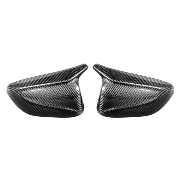
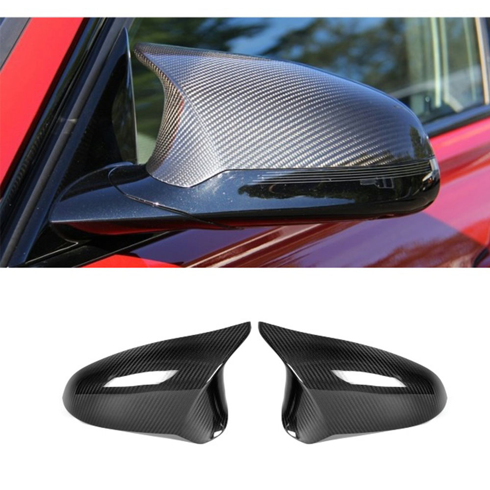
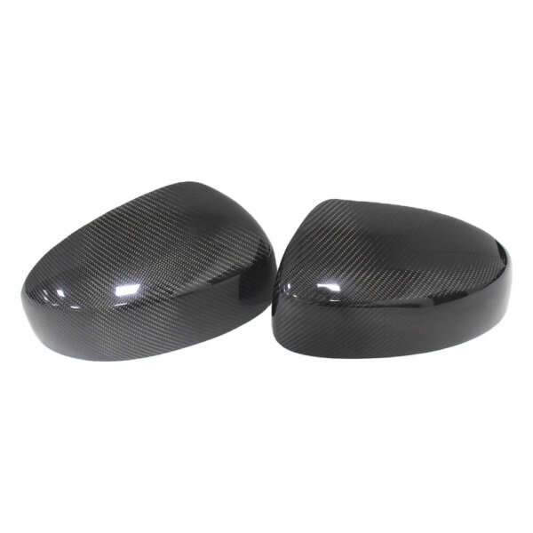
- Project type: Cosmetic and semi-structural automotive trim (interior panels, exterior covers) for a performance or specialty vehicle
- Material: 3K twill weave prepreg
- Process: Typically autoclave cure, for consistent resin content and a premium cosmetic surface with improved consolidation and lower void content
- Finish: Gloss or matte clear coat, depending on the customer’s specification
- Key engineering considerations: Matching exact OEM mounting points across compound curves, and keeping the visible weave pattern aligned and symmetrical across a matched set — a common failure point when panels are laid up without matched templates
Large Cosmetic/Structural Shell or Enclosure
- Project type: A large panel or enclosure for an industrial, equipment, or vehicle application
- Material: Sandwich construction with a foam or honeycomb core between two carbon skins
- Process: Vacuum infusion or prepreg molding, using a single shell or separately molded inner and outer skins depending on geometry, stiffness, and access
- Key engineering considerations: Large, mostly flat surfaces are prone to warping during cool-down; parting-line placement and a controlled cooling schedule are needed to hold flatness tolerance
What Should You Look for in a Carbon Fiber Parts Manufacturer?
Beyond the specific process used, a few supply-chain and capability factors tend to determine how smoothly a custom project actually runs:
- Integrated or closely coordinated tooling capability. When mold design, CNC machining of the master pattern, and mold manufacture happen within the same facility or a tightly coordinated local supply chain, there are fewer handoffs — and fewer opportunities for tolerances, finish specs, or revisions to get lost in translation between separate vendors.
- Controlled molding, trimming, and finishing. A manufacturer that closely manages layup, curing, CNC trimming, and surface finishing — whether performed directly or through consistently managed partners — can generally hold tighter control over consistency between batches than one that outsources these steps without oversight.
- Low-volume flexibility. Aftermarket, motorsport, and specialty industrial parts often need runs of tens or hundreds of units rather than tens of thousands. A manufacturer set up primarily for long single-part production runs may not be tooled or staffed efficiently for this kind of order pattern — ask directly how they handle multi-mold, multi-batch orders at your target volume.
- Clear, engineering-literate communication. Given the number of decisions in this article — process selection, ply orientation, tooling material, cure cycle — the supplier reviewing your project should be able to explain why they’re recommending a given approach, not just quote a price.
Which Carbon Fiber Manufacturing Process Should You Choose?
| Project requirement | Recommended starting point |
|---|---|
| A single cosmetic prototype | Wet layup or a vacuum-bagged laminate |
| Premium dry-carbon appearance | Prepreg with oven or autoclave cure |
| Lightweight structural part | Engineered prepreg/autoclave layup or matched compression molding |
| Large panel or shell | Vacuum infusion or prepreg, depending on load and finish requirements |
| Hollow tube | Roll wrapping, bladder molding, or filament winding |
| Complex geometry with a chopped-carbon appearance | Chopped-fiber compression molding |
| Hundreds to thousands of parts per year | Aluminum or steel matched tooling |
The right process cannot be chosen from appearance alone — two parts that look identical can require entirely different processes depending on load case, thickness, tolerance, and annual volume.
What Information Does a Manufacturer Need Before Quoting?
To get an accurate quote and avoid delays, it helps to have ready:
- STEP file (preferred) or 2D drawing with overall dimensions
- Structural or cosmetic use case
- Load requirements, if structural
- Target thickness and weight
- Operating temperature and environmental exposure
- Required surface finish
- Initial quantity and expected annual demand
- Critical tolerances
- Insert and hole locations
- Whether an original sample is available for reference or scanning
- Testing/documentation requirements
- Destination country for shipping
What Happens After You Send a CAD File?
- Engineering review — we check the model for draft angles, corner radii, wall thickness, and mating features
- DFM feedback — we flag anything that would cause defects or fitment problems and suggest design changes if needed
- Process recommendation — we recommend a manufacturing process and tooling approach based on Our Five-Factor Process Selection Framework, described above
- Tooling quotation — pricing for mold design and manufacture, based on the recommended process
- Prototype/first-article approval — a first sample is produced and reviewed against the CAD model and requirements before production tooling or volume production begins
- Production — parts are manufactured, finished, inspected, and shipped
How Long Does Carbon Fiber Parts Manufacturing Take?
Lead time is generally made up of: CAD review and DFM feedback, pattern/master model creation, mold manufacture, first sample production and approval, then production and finishing. For many custom projects, CAD and DFM review takes several working days, and tooling plus first-sample preparation commonly falls in the range of approximately 3–5 weeks after final design and tooling approval, for a straightforward, low-volume part. Production lead time after first-article approval then depends on quantity, mold count, cure cycle, and finishing requirements. Complex multi-piece structural tooling or large-format parts can take significantly longer than this baseline.
Frequently Asked Questions
Is autoclave carbon fiber always better than other methods?
No. For many high-performance prepreg parts, autoclave curing provides excellent consolidation and low void content, but it also costs more and isn’t necessary for every part — other closed-mold or high-quality processes can perform very well in the right application. The right choice depends on the part’s performance requirements, cosmetic needs, geometry, and production volume — not on assuming the most expensive process is automatically correct.
What is the difference between wet carbon fiber and dry carbon fiber?
In common automotive and aftermarket usage, “dry carbon” generally refers to parts made with pre-impregnated (prepreg) material cured under heat and pressure with tightly controlled resin content, producing a lighter, more consistent laminate — see our full breakdown of what dry carbon fiber is for more detail. “Wet carbon” refers to fiber that is hand-saturated with resin during layup, which is more affordable but has more variability in resin content and final weight.
Can a carbon fiber part be made without a mold?
Simple flat or near-flat shapes can sometimes be machined from cured flat sheet stock. Most complex or curved geometries still require a mold to achieve the correct shape and surface finish.
Can you manufacture a carbon fiber part from an original sample, without a CAD file?
Yes, typically through 3D scanning and reverse-engineering, or by creating a mold directly from the sample. This requires confirming upfront whether the sample can be handled, temporarily modified, or must remain undamaged throughout the process.
Why are carbon fiber molds expensive?
Tooling cost reflects CAD and parting-line design, CNC machining of the master pattern, mold material (which must withstand repeated cure temperatures), surface finishing, and first-article trial fitting — not just the raw material cost of the mold itself.
How thick should a carbon fiber part be?
There is no single correct thickness. It depends on part size, span, curvature, expected load, mounting method, and the manufacturing process used — thickness should come from an engineering calculation or established design guideline, not a rule of thumb applied to every part.
Can you make carbon fiber parts from photos only, with no CAD file or sample?
Photos can help with an initial feasibility check, but they generally aren’t enough for an accurate quote or production. Reliable quoting needs either a CAD file, a physical sample for 3D scanning, or a detailed drawing with real dimensions.
What file format do you need for carbon fiber manufacturing?
STEP is preferred because it preserves accurate engineering geometry. STL files are usable for visual reference but typically need to be rebuilt into a proper engineering model before tooling design starts.
Why is my carbon fiber part quotation higher than I expected?
Quotes are usually driven by tooling cost, order volume, finishing requirements, CNC trimming complexity, and inspection/documentation needs — not just the price of the raw carbon fiber material. Low order quantities in particular carry a higher tooling cost per part, since mold cost is spread across fewer units.
Can you make one prototype before committing to mass production?
Yes — building a first-article or small prototype run before committing to production tooling and full-volume manufacturing is standard practice, and is usually the safest way to validate fit, finish, and performance before scaling up.
Start a Custom Carbon Fiber Project
Contact us with your STEP file, target quantity, finish requirements, and application details for a preliminary manufacturability review.