
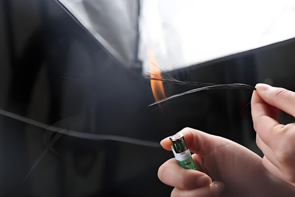

Carbon Fiber Composite Material Hot Pressing Molding Process
Our factory employs an advanced carbon fiber hot press process with a P20 steel mold, ensuring high efficiency, precision, durability, and cost-effectiveness for quality production.
We manufacture custom carbon fiber beams, I-beams, C-beams, box beams and structural profiles for industrial equipment, robotics, UAVs, aerospace interiors, marine structures, motorsport, and inspection and measurement systems. Every beam is engineered around the load direction, span, stiffness target, mounti ng method, surface finish, and production quantity — not pulled from a stock catalog.
If you already have a 2D drawing, a STEP/STP file, or an existing aluminum or steel beam you’re converting to CFRP, send it to us and we’ll review feasibility and provide an initial response within 24 hours. For complex custom beams, a formal quotation may require drawing review by our engineering team.
Need a quote? Send your cross-section drawing, STEP file, or specs. We’ll respond with an initial feasibility review within 24 hours. Request a Quote →
A carbon fiber beam is a structural profile manufactured from carbon fiber reinforced polymer (CFRP), designed to carry bending, torsional, or axial loads while reducing weight compared with metal alternatives. It’s used wherever engineers need to reduce moving mass, minimize deflection, improve vibration damping, or extend fatigue life beyond what steel or aluminum can offer.
Unlike an aluminum extrusion — which behaves identically in every direction — a carbon fiber beam is anisotropic: its stiffness and strength depend on fiber orientation. A beam with all fibers running along its length will be extremely stiff in bending along that axis but relatively weak in torsion. A balanced laminate with ±45° plies handles torsion better but trades off some axial stiffness. The layup schedule is part of the engineering work, not just a manufacturing detail.
Two properties that make CFRP beams particularly useful in engineering applications:
As a carbon fiber composite manufacturing factory, we produce structural beams alongside a wide range of custom carbon fiber parts for industrial, automotive, and aerospace customers. The most common cross-section profiles we produce are:
When requesting a quote, it helps to specify beams the way structural sections are normally described. The naming convention we use:
| Code Example | Type | Meaning |
|---|---|---|
| I-80×40×3 | I-beam | Height 80mm, Flange Width 40mm, Wall Thickness 3mm |
| H-120×80×4×6 | H-beam | Height 120mm, Flange Width 80mm, Web 4mm, Flange 6mm |
| C-60×30×2 | C-channel | Height 60mm, Flange Width 30mm, Wall Thickness 2mm |
| RHS-40×20×2 | Rectangular hollow section | 40×20mm outer, 2mm wall |
For custom sections, you can specify any combination of these dimensions in a drawing or STEP file, and we evaluate what tooling and process is needed to produce it.
Typical size ranges we work within:
The most common engineering question we encounter is whether switching from aluminum or steel to carbon fiber makes sense for a given application. Here is a direct comparison:
| Property | Carbon Fiber (CFRP) | 6061-T6 Aluminum | Structural Steel |
|---|---|---|---|
| Density | ~1.55–1.60 g/cm³ | 2.70 g/cm³ | 7.85 g/cm³ |
| Tensile strength (fiber direction) | 600–1,500 MPa (grade-dependent) | 310 MPa | 400–550 MPa |
| Tensile modulus (fiber direction) | 70–300 GPa (grade-dependent) | 69 GPa | 200 GPa |
| Specific stiffness (E/ρ) | Significantly higher than aluminum when optimized in the primary load direction | Baseline | ~50% of aluminum |
| Thermal expansion (longitudinal) | ~0–2 µm/m·K | ~23 µm/m·K | ~12 µm/m·K |
| Vibration damping | Generally higher than aluminum or steel; extent depends on laminate and structure | Low | Very low |
| Corrosion resistance | Excellent | Good (anodized) | Requires coating |
| Fatigue behavior | Excellent when properly designed | Moderate | Good |
| Electrical conductivity | Conductive in-plane | Conductive | Conductive |
| Galvanic compatibility with aluminum | Requires isolation layer in wet environments | — | — |
| Machining | Carbide/diamond tooling required | Standard CNC | Standard CNC |
| Joining method | Bonded or mechanical with engineered inserts | Welded, bolted, riveted | Welded, bolted |
| Custom profile tooling | Required for non-standard sections | Off-the-shelf extrusions available | Standard mill sections available |
| Unit cost (equivalent cross-section) | Higher | Lower | Lower |
Galvanic corrosion note: carbon fiber is electrically conductive in-plane. Direct contact between CFRP and bare aluminum in a humid or wet environment will cause galvanic corrosion of the aluminum. This is managed with GFRP shims, isolation washers, anodized interfaces, or wet sealant — something to design in from the start, not discover during service.
When carbon fiber makes sense: moving structures where reduced inertia means faster cycles or better accuracy (gantries, robotics, CMM bridges), precision structures where thermal movement causes errors (metrology, telescope mounts), structures where fatigue or corrosion degrades metal over time, and applications where weight reduction has a direct operational impact (UAV flight time, motorsport performance).
When metal is still the more practical choice: very short spans where weight saving is marginal, parts with complex 3D geometry that doesn’t suit a laminate layup, very low-quantity projects where tooling cost cannot be amortized, and applications with concentrated point loads at very small contact areas where inserts would add more cost than the material switch saves.
| Beam Type | Best Loading Scenario | Key Advantage | Main Trade-off |
|---|---|---|---|
| I-beam / H-beam | Single-axis bending; long spans | Most efficient use of material for bending stiffness | Lower torsional rigidity than closed box |
| C-beam / U-channel | Edge-mounted frames; rail guides; rib structures | Easy to bolt flat to surfaces; open section allows cable routing | Open section has lower torsional stiffness |
| Box beam | Combined bending and torsion; robotic arms; UAV booms | Highest torsional rigidity per unit weight | More complex tooling than open sections |
| Rectangular / square beam | General framing; jigs; test fixtures | Simple geometry; easy to machine and assemble | Not optimized for specific load directions |
| Hybrid beam with metal inserts | High-load bolted connections; flange-mounted assemblies | Reliable mechanical joint; designed-in bearing capacity | Higher per-part cost; requires insert design |
| Truss / lattice beam | Very long spans; overhead structures; wind-loaded structures | Optimized mass-to-stiffness; reduced wind resistance | More complex assembly; multiple member connections |
Before replacing an aluminum or steel beam with CFRP, or designing a new carbon fiber structural beam from scratch, these are the key design inputs that determine whether the switch makes sense and what the beam needs to look like:
If you can share even a partial picture of these inputs with your enquiry, we can give a more specific and useful initial response.
Span, supports, and load location. How long is the beam, how is it supported, and where is the load applied? A 1.5m gantry crossbeam under distributed load and a 1.5m cantilever arm under tip load require very different cross-sections and layups — the same length doesn’t mean the same design.
Bending stiffness vs. torsional stiffness. If the beam is primarily loaded in one plane, we optimize for axial stiffness with a high UD fiber content. If it experiences combined bending and torsion — typical for robotic arms, camera sliders, and UAV booms — we use a closed box section with ±45° plies to carry shear loads.
Fiber orientation and layup sequence. A beam with all 0° UD plies is the stiffest possible in the axial direction but can fail with little warning in the transverse direction. A quasi-isotropic laminate [0/45/90/-45]s is more damage-tolerant and easier to connect to surrounding structure, but heavier for the same axial stiffness. For most structural beams, we use a hybrid schedule: predominantly UD plies in the flanges for bending stiffness, ±45° plies in the web for shear, and outer cap plies for surface protection.
Wall thickness, cross-section proportions, and buckling. For thin-walled beams under compression or bending, local buckling can occur before the material reaches its failure stress. We review this during engineering assessment, especially for slender beams or those under compressive loading.
Attachment: holes, inserts, and bonding surfaces. A bolt through an unlined CFRP hole concentrates stress at the fastener and will fail in bearing at a much lower load than a properly designed insert allows. For any connection above light-duty, we recommend bonded metal inserts or local ply buildup at the attachment zone.
Operating environment. Standard epoxy resin systems hold their properties up to approximately 80–100°C. For higher-temperature environments, we select a resin system based on the material data sheet for the working temperature range. UV-exposed parts need UV-stable clear coat. Chemical exposure should be mentioned during enquiry — resin systems vary in chemical resistance.
Electrical conductivity. Carbon fiber is electrically conductive in-plane. If the application requires an electrically isolating beam — sensor mounts, RF-transparent structures, medical equipment — GFRP or hybrid CFRP/GFRP layups can address this.
This is one of the most common process questions we receive, and the answer matters for both cost and lead time.
Pultruded carbon fiber beams are produced by pulling continuous fibers through a resin bath and a heated die in a single continuous operation. The result is a constant cross-section profile with consistent properties along the full length. Pultrusion is cost-effective for high volumes of standard sections — I-beams, H-beams, C-channels, rectangular tubes — and produces a high, uniform fiber content. The limitation is geometry: the cross-section must be constant along the length, and the process does not allow local reinforcement, varying wall thickness, or integrated inserts within the beam body.
Molded carbon fiber beams — produced by autoclave, compression press, or wet layup — offer much greater design flexibility. The layup can be varied along the length, local reinforcement can be added at attachment points, metal inserts can be incorporated during manufacturing, and a visible surface finish is achievable on all faces. Molded beams are better suited to custom I-beams, C-beams, and box beams where geometry changes along the length or where the quantity doesn’t justify pultrusion tooling.
| Scenario | Better Process |
|---|---|
| Long, constant cross-section in high volume | Pultrusion (via partner) |
| Custom geometry, inserts, or visible surface | Autoclave or compression molding |
| Small quantity custom I-beam or C-beam | Compression molding |
| Prototype with final production intent | Molded (same mold for production) |
| Very long structural stock (meters of profile) | Pultrusion (via partner) |
For most custom beam projects — UAV booms, gantry beams, robotic arm links, inspection fixtures — molded processes are the better starting point. We’ll identify the right process during engineering review.
| Process | Best Geometry | Performance Level | Tooling Cost | Min. Practical Qty | Max. Length |
|---|---|---|---|---|---|
| Prepreg autoclave | Complex profiles; visible surfaces | Highest | Medium–High | 1+ | ~2,500mm |
| Compression / hot press | I-beams; C-beams; close-tolerance profiles | Very good | Medium–High | 10+ | ~2,000mm |
| Wet layup + vacuum bag | Large one-offs; prototypes | Good | Low | 1 | ~3,000mm+ |
| Pultrusion (via partners) | Constant cross-section stock; volume | Very consistent axial properties | High (one-time) | 50m+ | Continuous |
Carbon fiber prepreg plies — typically T700 3K twill for visible surfaces, T700 UD or T800 UD for structural flanges where stiffness-to-weight is critical — are hand-laid into the mold, vacuum-bagged, and cured in an autoclave under controlled temperature and pressure. This process produces consistent consolidation and minimizes voids. It’s our standard approach for performance-critical beams, visible-surface parts, and anything requiring precisely controlled layup orientation.
For I-beams and C-channels where the flange and web geometry must be dimensionally precise and repeatable across a batch, we use matched steel or aluminum tooling under a hydraulic press. Prepreg is laid into the mold halves, and the press applies even clamping pressure during cure. This gives tighter cross-section tolerance and good part-to-part consistency — important when the beam must fit into a machine with close clearances or mate to a precision interface.
For prototypes, large single beams, or projects where budget doesn’t support autoclave tooling, wet layup with vacuum bagging is practical. Consolidation is somewhat lower than autoclave, which means slightly lower properties per unit weight, but for many structural applications the difference is within acceptable margins. We use this process where it genuinely fits the project requirements.
For long constant cross-section profiles — structural frames, rail systems, and guide tracks — pultrusion delivers consistent properties at high volume. We don’t operate pultrusion equipment in-house; for projects requiring pultruded profiles, we source through qualified partners and manage quality on your behalf.
After curing, most beams need secondary work before delivery: trimming to length, drilling mounting holes, milling slots, bonding inserts. We use carbide and diamond-tipped tooling to avoid delamination at cut edges. For production quantities, CNC drilling with fixtures ensures consistent hole position and quality. End fittings are CNC-machined to GD&T tolerances and then bonded or bolted to the beam body.
Most structural carbon fiber beams don’t fail in the beam body — they fail at the connection point. This is why we treat end fitting design as part of the beam project, not a detail to be resolved later.
For beams attaching to machine structures, gantry carriages, robotic joints, or UAV fuselages, the interface typically involves one or more of the following:
The end fitting geometry often affects the tooling design for the beam body itself. We review your attachment method during engineering assessment and flag anything that could create load path issues, insufficient bonding area, galvanic contact, or tolerance problems.
Achievable tolerance depends on the profile, length, process, and whether post-machining is included:
| Feature | As-produced (molded / roll-wrapped) | After CNC machining |
|---|---|---|
| Outer dimensions | ±0.2–0.5mm typical | ±0.05–0.1mm achievable |
| Wall thickness | ±0.1–0.3mm | — |
| Length | ±1–2mm (cut to length) | ±0.1mm |
| Hole position | — | ±0.05mm with fixture |
| Straightness | ≤0.5mm/m typical | Depends on beam stiffness |
| Surface finish (visible) | 3K weave, glossy or matte clear coat | — |
For beams going into precision machines or inspection systems, the critical interface dimensions — hole positions, end fitting mating surfaces, rail mounting faces — are CNC-machined to the tolerances the application requires.
Standard inspection: dimensional check on critical dimensions, visual inspection for surface defects (voids, resin-rich areas, dry fiber, delamination at edges), weight check, and photographic documentation. For production batches, we issue a first-article inspection report for customer approval before running the full batch.
We don’t currently offer in-house non-destructive testing (ultrasonic C-scan or X-ray). For projects where this is specified, we can arrange third-party inspection — this should be discussed during the quotation stage as it affects cost and schedule.
We prefer to explain these before a project starts rather than after.
Impact damage is hard to detect. Carbon fiber composites don’t yield like metal before failing — they fracture. A tool dropped onto a beam or a lateral impact can cause internal delamination that doesn’t show on the surface but reduces structural capacity. If the beam operates in an impact-prone environment, we can discuss damage-tolerant design measures, protective covers, or whether a metal alternative is more practical.
Point loads require inserts or load-spreading provisions. A bolt pulled through a thin CFRP wall without a proper insert will fail in bearing at a fraction of the load a threaded insert can carry. Any bolted connection under significant load needs to be designed with this in mind from the start.
Sharp internal corners complicate layup. Carbon fiber prepreg doesn’t conform cleanly to internal radii below about 3mm without risk of voids or resin-rich zones. We’ll flag this and suggest radius adjustments during design review if it applies.
One-piece length is process-limited. Our equipment accommodates up to approximately 2,500mm for most profiles. For longer spans: pultruded profiles via partners (for constant sections), spliced sections, or truss designs that break the span into shorter members.
CFRP-to-aluminum contact in wet environments causes galvanic corrosion. This is a design requirement, not an installation detail. Isolation must be built into the joint from the start.
Custom I-beams and C-beams require dedicated tooling. For structural rectangular tubes in standard sizes, existing mandrels reduce tooling cost and lead time. For custom I-beam and C-channel cross-sections, tooling is a one-time investment that needs to be justified by the production plan.
The following are anonymized project patterns based on our manufacturing experience. Customer names, drawings, and specific dimensions are not published — most custom structural beam projects are covered by NDA.
The design goal was to reduce moving mass in a 1,200mm aluminum gantry crossbeam and improve dynamic settling behavior during high-speed passes. We produced a carbon fiber box beam with predominantly UD prepreg in the top and bottom flanges for bending stiffness, ±45° layers throughout for torsional stability, and bonded aluminum end plates with CNC-drilled mounting holes for the gantry carriage interface. The low CTE of CFRP was selected to reduce temperature-related dimensional movement during long production shifts. Process: prepreg autoclave.
A commercial UAV program needed structural booms for a payload-lifting multirotor, with stainless steel threaded inserts at each end for motor mount and fuselage attachment. The project started with four prototype booms for flight validation. We produced the booms by roll-wrapping T700 prepreg over a mandrel, with additional UD ply buildup at the insert zones. After curing, stainless inserts were bonded with structural adhesive and mounting holes CNC-drilled to final position. After prototype sign-off, the program moved to batch production. From drawing approval to first prototype delivery: approximately four weeks.
A racing team needed a structural beam routed close to the exhaust system, with a sustained working temperature that would exceed standard epoxy limits. We selected a high-Tg resin system based on its data sheet properties for the application temperature range and produced the beam by compression molding with a steel mold. Surface: matte clear coat over 3K twill. This type of high-temperature engineering work is one aspect of our broader carbon fiber motorsport and automotive program.
An astronomical equipment manufacturer needed structural members for a motorized telescope mount where thermal movement between day and night temperatures caused tracking errors. The low longitudinal CTE of CFRP was the key design requirement. We produced rectangular tube sections in a predominantly 0° UD layup to maximize axial stiffness and minimize longitudinal thermal expansion. Outer surfaces were left sanded to allow the customer to apply their own anodized aluminum interface brackets with GFRP isolation washers.
Industrial automation and robotics. Gantry crossbeams, linear motor carriages, robotic arm links, SCARA cross-members, and delta robot arms. Reducing moving mass in these systems can contribute to faster cycle times, lower motor torque requirements, and better position repeatability. Low CTE also benefits precision inspection systems where thermal movement affects accuracy.
UAV and drone structures. Fixed-wing wing spars, multirotor arms and booms, payload rails, and fuselage longerons. We work with teams at prototype stage and in small-batch production for commercial UAV programs.
Aerospace and aircraft structures. Cabin frames, seat structures, equipment racks, and non-primary structural members. For dedicated aircraft C-beam and structural profile applications, see our carbon fiber aircraft C-beam page. We don’t certify parts for primary aircraft structure, and we’re clear about that distinction in every aerospace enquiry.
Marine and offshore. Spars, booms, outrigger arms, and hatch frame structures. Corrosion resistance combined with weight saving makes carbon fiber practical for racing sailboats, tenders, and offshore equipment exposed to both saltwater and cyclic loading.
Motorsport and racing. Structural chassis members, roll cage inserts, splitter support arms, undertray structure, and suspension pickup reinforcements. We produce carbon fiber parts for cars and track vehicles as well as carbon fiber motorcycle components — structural beams are part of a broader capability in performance vehicle composites.
Metrology and precision measurement. CMM bridges, profilometer arms, telescope tube assemblies, and precision stage beams. The near-zero CTE and high specific stiffness of carbon fiber make it well-suited where thermal movement or elastic deflection create measurement errors.
Printing, textile, and converting machinery. Doctor blades, dancer rollers, web guide beams, and print cylinder supports. In high-speed web processing machines, carbon fiber can reduce vibration and inertia, improving print registration and reducing web-edge oscillation.
| Option | Available Choices |
|---|---|
| Carbon fiber grade | T300, T700, T800, M40J, or equivalent specified by properties |
| Fiber form | UD prepreg (highest axial stiffness), 3K plain weave, 3K twill, 12K large-tow, spread-tow |
| Layup orientation | 0° UD dominant, ±45°, quasi-isotropic [0/45/90/-45]s, or hybrid per load case |
| Resin system | Standard epoxy, high-Tg epoxy, fire-retardant epoxy — selected per working temperature and data sheet |
| Surface finish (visible) | Glossy clear coat, matte clear coat, UV-protective clear coat |
| Surface finish (structural/bonding) | Raw, sanded for bonding, primed |
| Color | Natural carbon weave (clear coat), solid paint (specify RAL or supply sample), custom |
| Metal inserts | Aluminum, stainless steel, titanium — bonded or co-molded |
| End fittings | Precision-machined aluminum or steel end fittings to your drawing and GD&T tolerances |
| Galvanic isolation | GFRP shim layers, isolation washers, or anodized interfaces at CFRP-to-aluminum joints |
| Mold material | Composite mold (prototype / low-volume), aluminum mold (medium volume), P20 steel mold (high volume / tight tolerance) |
| Secondary machining | CNC drilling, milling, slotting, tapping; inserts bonded and machined to position |
| Inspection and documentation | Dimensional check, visual inspection, first-article report, weight tolerance, material traceability |
| Information | Why It Matters |
|---|---|
| 2D drawing or STEP/STP file | Evaluates mold geometry, layup access, and CNC operations |
| Cross-section type and dimensions | Determines tooling, fiber schedule, and stiffness |
| Wall thickness | Affects structural performance, weight, and tooling |
| Beam length per piece | Determines process choice and shipping method |
| Load case, target stiffness, or deflection limit | Drives fiber orientation and cross-section design |
| Mounting / attachment method at each end | Determines insert type, end fitting design, and local reinforcement |
| Quantity: prototype / pilot batch / production | Determines mold investment and unit pricing |
| Surface finish and color | Affects processing steps and cost |
| Working temperature range | Determines resin system |
| Tolerances on critical features | Drives tooling investment and post-machining scope |
| Electrical isolation required? | Determines if GFRP layers or hybrid layup is needed |
| Existing sample or part for scanning? | 3D scanning available if no drawing exists |
If you don’t have all of this yet — for example, you have an existing aluminum beam with no formal drawing — send us what you do have. We can work from a sketch with key dimensions, photos with measurements, a physical sample for scanning, or a description of the application and the performance target.
Step 1 — Submit your requirements. Email your drawing, STEP file, or project description. For straightforward enquiries, we’ll provide an initial response within 24 hours.
Step 2 — Engineering review and quotation. We review the design for manufacturability, process fit, and connection design — flagging anything that affects performance, cost, or feasibility before quoting. You receive a formal quotation with tooling cost (if applicable), unit price, and confirmed lead time.
Step 3 — Tooling development. For custom profiles requiring dedicated tooling, we design and manufacture the mold from the approved drawing. Tooling remains at our facility and is available for all future reorders at no additional tooling charge.
Step 4 — First-article sample. We produce a first-article part, share dimensional inspection results and photographs, and wait for your approval before proceeding to batch production.
Step 5 — Batch production and inspection. Production with inspection at defined checkpoints. Inspection results and photographs are documented per agreed quality plan.
Step 6 — Packaging and shipping. Long beams are packed with internal support, foam padding, and wooden crating where needed. We ship regularly to the US, UK, Germany, Canada, and Australia and handle all export documentation.
We are a carbon fiber composite manufacturing factory — not a trading company and not a stock reseller. Learn more about our factory and production capability →
Our facility runs autoclaves, compression presses, and CNC machining equipment, and we produce CFRP parts across automotive, motorcycle, UAV, industrial, and sports equipment programs. Beyond structural beams, our custom carbon fiber manufacturing service covers everything from one-off prototypes to OEM batch production across a wide range of part types and industries.
What this means for a structural beam project:
Both profiles have the same cross-section shape — two flanges connected by a vertical web. The naming convention differs by proportion: I-beams typically have narrower flanges relative to the web height, while H-beams have flanges closer in width to the total height, giving a more symmetrical appearance. In carbon fiber, this distinction is less standardized than in structural steel sections; we produce whichever flange and web proportions your design specifies.
On a weight-for-weight basis, the tensile strength and stiffness of carbon fiber along the fiber direction are significantly higher than structural steel. In absolute terms (per unit of cross-section area), the comparison depends on fiber grade, layup, and load direction. For most structural beam applications, the more useful metric is bending stiffness-to-weight, where carbon fiber performs well when the beam is designed to take advantage of its directional properties.
Rarely at the same dimensions. Carbon fiber and aluminum have different modulus values and very different directional behavior, so a dimensional swap will change deflection behavior. Most aluminum-to-CFRP conversions involve redesigning the cross-section to achieve the same or better stiffness at lower weight — which typically means different section proportions, wall thickness, and layup. If you share your current aluminum beam specification and the stiffness or deflection requirement, we can help with this assessment.
Yes, and this is one of the most common structural beam applications we see. CFRP gantry crossbeams reduce moving mass, which allows higher acceleration and deceleration without exceeding motor limits, and reduces settling time after each positioning move. The low CTE also reduces thermal-induced positioning drift in temperature-varying production environments. The specific design — cross-section, layup, end fitting geometry — depends on span, rail mounting method, deflection target, and machine dynamics.
There is no universal answer — it depends on the load case. A practical starting point for a beam loaded primarily in bending is predominantly 0° UD plies in the flanges (where bending stress is highest) combined with ±45° plies in the web (for shear capacity and torsional resistance), and outer cap plies for surface quality. If the beam also carries torsional load, we increase the ±45° content. If axial compressive load is significant, 90° plies may be added to resist local buckling. The final layup schedule is determined during engineering review after we understand your load case.
Yes. If you don’t have drawings, we can work from a physical sample, photographs with key dimensions, or a 3D scan. For a true aluminum-to-carbon conversion, we’ll also need to understand the load case and target stiffness or deflection — because a carbon fiber beam is not usually a direct dimensional replacement. The geometry is typically redesigned to optimize for the material’s properties.
A drawing speeds up the process, but it’s not required to start. A sketch with the key dimensions — cross-section type, height, flange width, wall thickness, length, and attachment point locations — is enough for an initial feasibility assessment. If you have an existing part but no drawing, we can 3D scan it.
Yes. Prototype and first-article orders are a standard part of our process. For tooled profiles, the prototype is built on the same mold used for production, so it is fully representative of the final part.
For roll-wrapped tubes in common sizes, there is no hard minimum — single pieces are possible. For custom-tooled profiles, the tooling cost is a fixed element that makes very small runs less economical. We’ll be direct about whether the project is feasible at your quantity.
No. Tooling is a one-time cost. The mold stays at our facility and is available for all reorders without additional tooling charges. The tooling amortization terms are stated in the quotation.
Yes, with the correct tooling and technique. We use carbide or diamond-tipped drills at controlled feed rates, with backup support on the exit face to prevent delamination at breakthrough. For production quantities, CNC drilling with fixtures ensures consistent hole position and edge quality.
No. CFRP cannot be welded. Joints are made by structural adhesive bonding, mechanical fasteners through designed inserts, or a combination of both. For structural joints that need to be disassembled, bonded metal inserts with threaded fasteners are the standard approach.
For standard rectangular tubes in common sizes: typically 1–3 weeks. For custom profiles requiring new tooling: approximately 3–5 weeks for first-article samples after drawing approval, then 2–4 weeks for batch production. Confirmed timelines are included in every quotation.
Yes. We provide material traceability documentation for the carbon fiber prepreg used in production. For projects requiring third-party mechanical testing of produced parts, this should be discussed and agreed during the quotation stage, as it affects cost and lead time.
Isolate the contact interface. Options include a GFRP shim between the carbon beam and the aluminum mounting surface, anodized aluminum at the interface, isolation washers at each fastener, or a wet sealant in the joint. The right approach depends on the joint geometry and level of environmental exposure. We’ll specify isolation measures as part of the end fitting design where your assembly creates a CFRP-to-aluminum contact in a potentially wet or outdoor environment.
Send your drawing or STEP file to [email protected] or use the contact form below. Include cross-section dimensions, wall thickness, length, quantity, surface finish requirements, and any end fitting or mounting details. We’ll respond with an initial feasibility review within 24 hours. For complex custom beams, a formal quotation follows after drawing review by our engineering team.
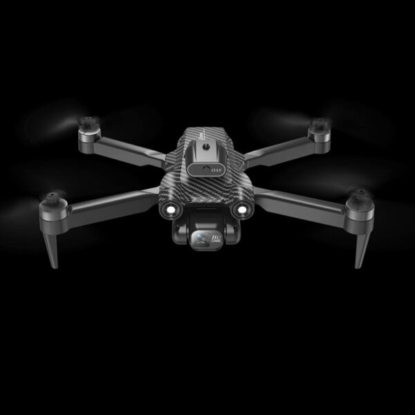

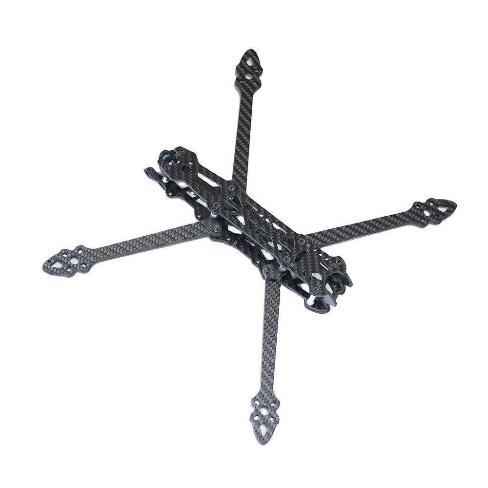
Our factory employs an advanced carbon fiber hot press process with a P20 steel mold, ensuring high efficiency, precision, durability, and cost-effectiveness for quality production.
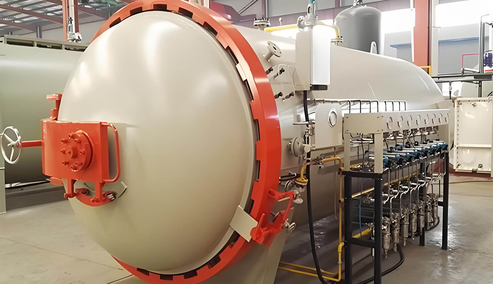
Our factory runs 100+ hot pressure autoclaves, using aluminum molds and vacuum induction to shape carbon fiber with precision. High heat and pressure enhance strength, stability, and flawless quality.
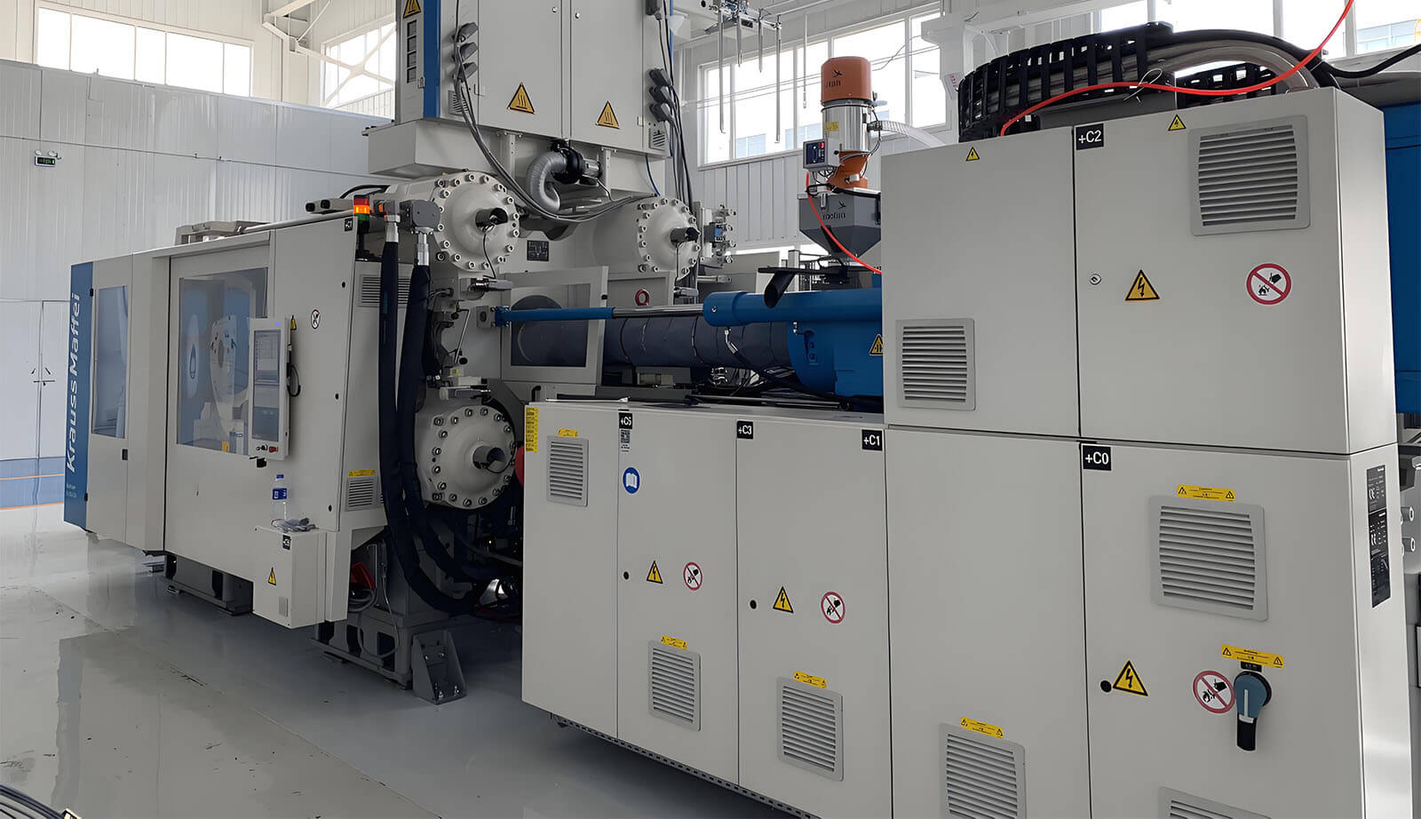
Our Carbon Fiber Research Center drives innovation in new energy, intelligence, and lightweight design, using advanced composites and Krauss Maffei FiberForm to create cutting-edge, customer-focused solutions.
Here are the answers to the frequently asked questions from the experienced carbon fiber products factory
We produce a wide range of carbon fiber components, including automotive parts, motorcycle parts, aerospace components, marine accessories, sports equipment, and industrial applications.
We primarily use high-quality prepreg carbon fiber and large-tow carbon fiber reinforced high-performance composites to ensure strength, durability, and lightweight characteristics.
Yes, our products are coated with UV-protective finishes to ensure long-lasting durability and maintain their polished appearance.
Yes, our facilities and equipment are capable of producing large-size carbon fiber components while maintaining precision and quality.
What are the benefits of using carbon fiber products?
Carbon fiber offers exceptional strength-to-weight ratio, corrosion resistance, stiffness, thermal stability, and a sleek, modern appearance.
We cater to automotive, motorcycle, aerospace, marine, medical, sports, and industrial sectors with a focus on lightweight and high-performance carbon fiber components.
Yes, we provide custom carbon fiber solutions tailored to your specifications, including unique designs, sizes, and patterns.
We utilize advanced technologies such as autoclave molding, hot pressing, and vacuum bagging, ensuring precision, stability, and quality in every product. wonders with the Hello Elementor Theme, we’re trying to make sure that it works great with all the major themes as well.
We use aluminum and P20 steel molds, designed for durability and high accuracy, to create complex and precise carbon fiber components.
Our products undergo rigorous quality control checks, including dimensional accuracy, material integrity, and performance testing, to meet industry standards.